Universal winding machine for a multitude of tray designs

a tray winding machine and tray design technology, applied in the field of surgical sutures and surgical needle packaging, can solve the problems of not allowing for other packaging designs, unable to allow for variations in the dimensions of tray packages, and the rpm (rounds per minute) that the package can be run, so as to achieve the effect of easy adaptation

Active Publication Date: 2019-02-07
HARRO HOFLIGER VERPACKUNGSMASCHEN
View PDF10 Cites 2 Cited by
  • Summary
  • Abstract
  • Description
  • Claims
  • Application Information

AI Technical Summary

Benefits of technology

[0011]Proceeding from this previously known prior art, it is an object of the present invention to provide a novel suture winding machine which can be easily adapted for different designs of tray packages and which is useful in a high-speed packaging process for packaging surgical sutures.

Problems solved by technology

Although conventional winding processes with winding fixtures and styluses perform adequately for their intended use, there may be deficiencies associated with such winding processes.
This does not allow for other designs of packages such as a plastic tray consisting of a single piece bottom only or a side loaded package.
The opening of the flaps influences the rpm (rounds per minute) that the package can be run at due to damage caused as the stylus impacts and pushes the flaps up.
Also for example, a stylus in a conventional winding fixture is rigidly mounted to the winding fixture and this does not allow for variations in the dimensions of tray packages.
This may also result in potentially improper placement of the suture in the track of the package.

Method used


Image

  • Universal winding machine for a multitude of tray designs
  • Universal winding machine for a multitude of tray designs
  • Universal winding machine for a multitude of tray designs

Examples


Embodiment Construction

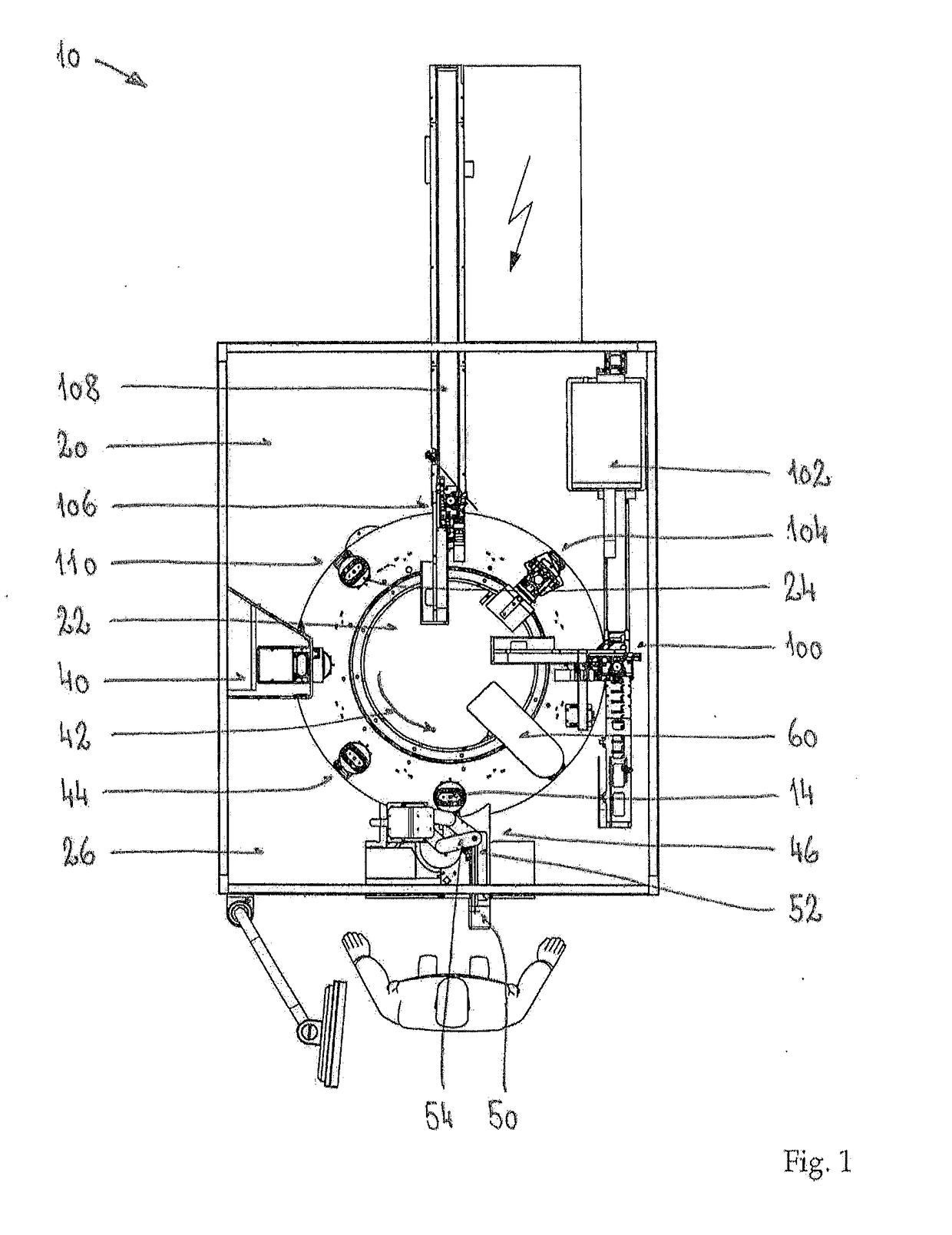
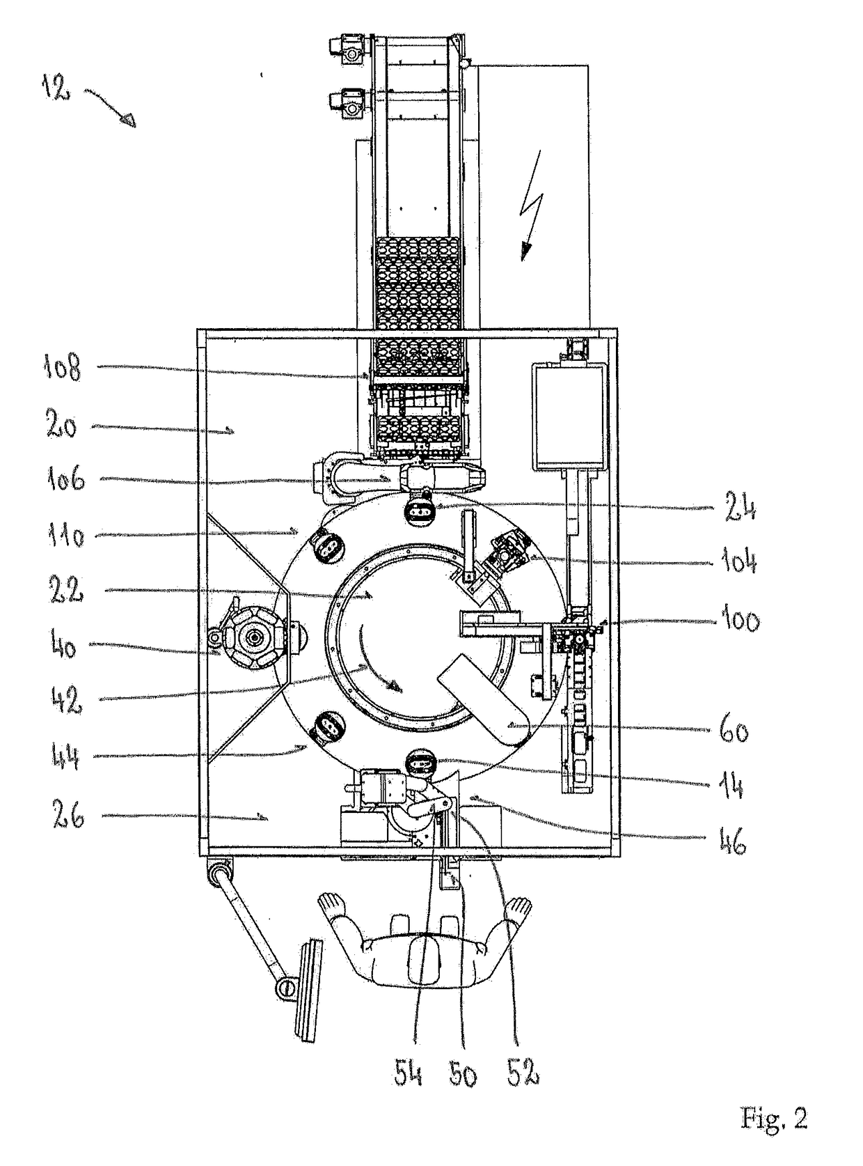
[0039]The winding process of the present invention can be used in a manual suture winding machine 10 according to FIG. 1 or in a semi-automatic suture winding machine 12 according to FIG. 2. In both cases, tray suture packages 14 of various designs can be used. The shape of the tray 14 can be essentially circular to oval. It can also be oval with finger indentations on the outer periphery (peanut shape).

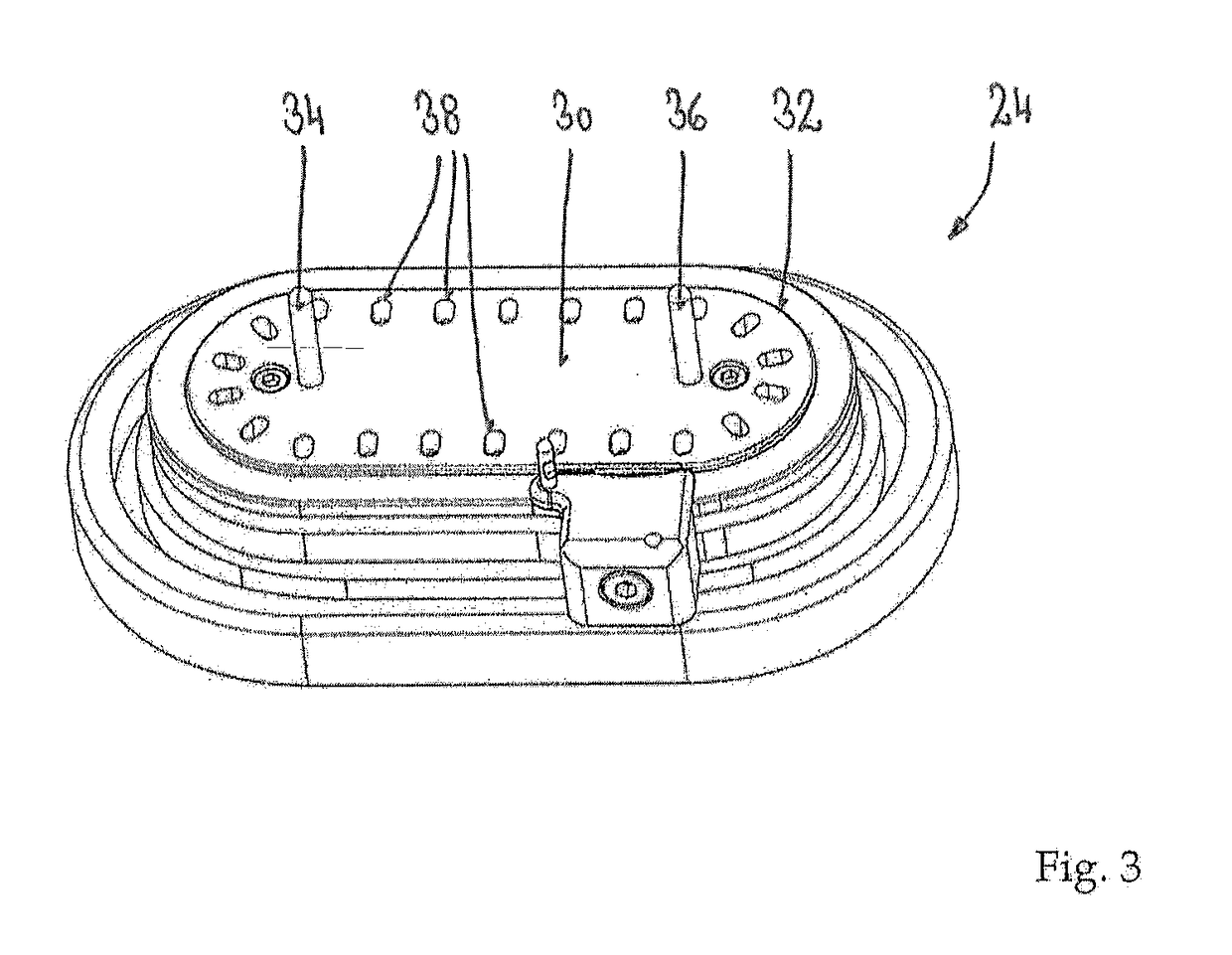
[0040]Referring to FIG. 1, the manual suture winding machine 10 has a base platform 20 with a rotary dial 22 mounted thereon. In this preferred embodiment there are eight package nests 24 on the rotary dial 22. Each of the package nests 24 is labelled so it will be possible to track the trays 14 during the winding process. There could be more than eight package nests 24 or less than this, depending on the number of stations necessary for the winding process.

[0041]This type of rotary dial 22 is widely used in the art so it is not described in detail. On the outside of the rotary dial ...


PUM


Abstract

A machine for winding suture into a suture tray package includes a base platform with package nests, each nest including upwardly-extending locating pins. A workstation places an empty tray onto one nest. Another workstation feeds a needle with attached suture in the tray and parks the needle in the tray. A winding station for winding the suture into a tray winding channel includes a rotatable winding head with configurable suture guiding pins, a stripper plate pushing the wound suture off the guiding pins, a suture control arm with proximal and distal ends and top and bottom sides, the distal end having a front standoff and a rear standoff incorporating a suture guiding channel, and a base member mounting the arm to base platform. A lid placement station places a lid onto a nest, a lid attachment station attaches lid to tray and an offloading station removes trays from nests.

Description

CROSS REFERENCE TO RELATED APPLICATIONS[0001]Applicant claims priority under 35 U.S.C. § 119 of European Application No. 17001348.6 filed Aug. 1, 2017, the disclosure of which is incorporated by reference.BACKGROUND OF THE INVENTION1. Field of the Invention[0002]This invention relates to packages for surgical sutures and surgical needles, more particularly to equipment for winding surgical sutures and attached surgical needles into suture packages. Conventional surgical suture and needle packages serve several useful functions, including protecting the needles and sutures during handling, shipping, and storage. In addition, the packages facilitate access and release of the needles and sutures during surgery or other medical procedures prior to application. The packages may be used for surgical sutures armed with surgical needles or for unarmed surgical sutures without needles.2. Description of the Related Art[0003]Surgical needles and attached surgical sutures are well known in the ...

Claims


Application Information

Patent Timeline
Patent Type & Authority Applications(United States)
IPC IPC(8): B65B63/04B65H54/04A61B17/06B65H54/22
CPCB65B63/04B65H54/04A61B17/06114B65H54/22A61B2017/00526A61B2017/06142B65H54/58B65H2701/3918A61B17/06133
Inventor DEY, CLIFFORDGATTNAR, JUERGENWAECHTER, BERNHARD
Owner HARRO HOFLIGER VERPACKUNGSMASCHEN
Why Eureka
Try Eureka