Systems, methods, and devices for remote health monitoring and management using internet of things sensors

a technology of health monitoring and internet of things, applied in the field of body sensor tracking and monitoring platforms, can solve problems such as largely limited

Active Publication Date: 2019-02-14
AMRITA VISHWA VIDYAPEETHAM
View PDF10 Cites 26 Cited by
  • Summary
  • Abstract
  • Description
  • Claims
  • Application Information

AI Technical Summary

Benefits of technology

[0011]In one embodiment the method comprises sensing electrocardiology (ECG) data by one sensing node, and sensing photoplethysmography (PPG) data by another sensor. Also in one embodiment the method comprises one sensor operating as a master sensor, and one or more other sensors operating as slave sensors, the master sensor receiving data from the slave sensors and transmitting the received data to the gateway. In one embodiment sensors transmit by one of ZigBee™, Bluetooth™ or WiFi protocol. In one embodiment he gateway transmits by one of cellular, radio frequency or Internet protocol. In one embodiment a first program executing on the gateway accomplishes rapid summarization of data for transmission to one remote destination as personalized health motifs (PHM), and a second program computes criticality alerts from the PHM data. And in one embodiment the summarized data is transmitted from the gateway to a cloud-storage and processing center, and the criticality alerts are transmitted by a second data network to doctor's platforms.
[0012]In one embodiment of the method the gateway is accomplished by a smartphone executing software providing functions of the gateway. In one embodiment the doctor's platforms execute Android-based SW enabling the doctors to receive and visualize patient data, and to suggest interventions remotely to the patients or their caretakers. And in one embodiment the Android-based SW also enables the doctors to set and tune sensing frequency, transmission timing, summarization intervals, and other variables in the system.

Problems solved by technology

Although systems for managing medical conditions have been described, they are largely limited to urban areas with good infrastructure and connectivity.

Method used


Image

  • Systems, methods, and devices for remote health monitoring and management using internet of things sensors
  • Systems, methods, and devices for remote health monitoring and management using internet of things sensors
  • Systems, methods, and devices for remote health monitoring and management using internet of things sensors

Examples


example 1

for Determining CM and CAM

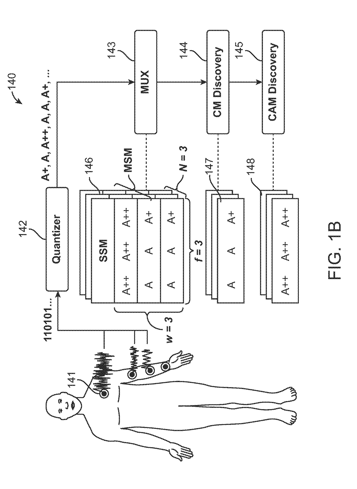
[0094]Using the comparison of individual data points as illustrated above, A*1 is compared with A*(1+I), A*(1+(2×I)) etc. In the problem of CM and CAM discovery in SSM, we assume I=f. The first row of sequences is compared with the other rows in a temporally ordered row wise comparison. To discover CM and CAM in SSM, a Hamming distance based algorithm was used as illustrated here:

Input: SSMInitialize:L = f; HammingDistMat = [0,0]W×W; dNOR [0]W×1; SumMat[0]W×1; CM_Index = 0; CAM_Index = 0;Procedure: FindHammingDistancesfor i = 1 to Wfor j = i to WHammingDistMat [i, j] = HammingDist (SSM [i], SSM [j])HammingDistMat [i, j] = HammingDistMat [j, i]dNOR [i] = HammingDist (SSM [i], MNOR)end forend forfor i = 1 to WSumMat [i] = sum (HammingDistMat [i, ...])end forProcedure: FindCMfor k = 1 to Windex = find_K-th_minimum (SumMat, k)if (dNOR (index) ≤α)CM_Index = indexbreakend ifend forProcedure: FindCAMfor k = 1 to Windex = find_K-th_minimum (SumMat, k)if (dNOR (inde...

example 2

y Quantization Technique for Continuous ECG Monitoring

[0096]A continuous monitoring ECG sensor as shown in FIG. 6A, SN is utilized. Suppose we intend to monitor a number of different parameters, P1, P2, Pi, such as RR interval, ST deviation, ST segment etc. Let us also assume that the total number of parameters is NP. The multi-parameter data is summarized and any criticality is identified such that a lucid report is sent to the doctors. Before abnormalities are found, the sensor data is preprocessed as follows.

[0097]First, the raw sensor data is processed by the parametric analyzer, which calculates the values of each parameter Pi, at a frequency of fP. Next, these parameter values are quantized into any of K severity symbols defined for the respective parameters (by the severity quantizer). The severity symbols are assigned as A+, A++, A−, A−− etc., based on the deviation from the medically accepted normal parameter value, which is denoted by the symbol A. The + and − symbols repr...

example 3

for Remote Monitoring of Vital Parameters in Patients

[0104]A single sensor (ECG sensor) was used an example, as illustrated in FIG. 7. The system supports multiple sensors in a similar manner. A low power wearable device with 2 to 4 electrodes was attached to the body of the patient. The power management includes a buck-boost voltage regulator, a battery charge controller, and a battery fuel gauge. The main controller is an MSP430 microcontroller with SPI, ADC, I2C, timers and GPIO. An optional temperature sensor provides the body temperature monitoring. An extremely power sensitive firmware controls this device and manages its connectivity to the mobile phone.

[0105]A number of patients are remotely monitored through the system by a number of doctors and / or nurses. Each patient is provided with a wearable, battery-powered, and wireless data aggregation and transmission unit, which is worn as a necklace or placed on the waist. The body sensors are connected to the data aggregation an...


PUM


Abstract

A health-monitoring system has IoT-vitals sensing nodes joined to a patient's body, sensing vital characteristics, employing wireless transmission circuitry transmitting sensed data by a short-range network, and a local gateway having wireless circuitry receiving transmitted data from the IoT-vitals sensors, software (SW) executing on a processor from a non-transitory medium, the SW processing the transmitted data received, and transmission circuitry transmitting processed data over a long-range network.

Description

CROSS-REFERENCE TO RELATED APPLICATIONS[0001]The present application claims priority to co-pending U.S. patent application Ser. No. 16 / 103,159, filed Aug. 14, 2018, which claims priority to Indian Patent Application No. 201741028828, filed on Aug. 14, 2017. All disclosure of the parent cases is incorporated herein at least by reference.FIELD OF THE INVENTION[0002]The invention generally relates to body sensor tracking and monitoring platforms, and in particular, to health monitoring systems, methods, and devices to remotely monitor and track patient health status.DESCRIPTION OF RELATED ART[0003]Present healthcare technologies allow for body sensors or implants attached to a patient to be used in medical monitoring and detection of emergency conditions in at-risk patients. However, the patient usually has to present himself at a local healthcare facility for accurate measurements, gain access to Hospital Information Systems (HIS) and advanced analytics, and subsequently wait for the ...

Claims


Application Information

Patent Timeline
Patent Type & Authority Applications(United States)
IPC IPC(8): A61B5/00A61B5/0205H04L29/08G16H40/67A61B5/046A61B5/361A61B5/363A61B5/364A61B5/366
CPCA61B5/0022A61B5/0205H04L67/12G16H40/67A61B5/046A61B5/0468A61B5/0006H04L67/322H04L67/18H04L67/30A61B5/14532A61B5/0472A61B5/0464G16H40/63G16H50/20A61B5/0024A61B5/7275A61B5/364A61B5/366A61B5/361A61B5/363H04L67/52H04L67/61
Inventor RAMESH, MANEESHA VINODINIPATHINARUPOTHI, RAHUL KRISHNANRANGAN, EKANATH SRIHARIP, DURGARANGAN, P. VENKAT
Owner AMRITA VISHWA VIDYAPEETHAM
Why Eureka
Try Eureka