Carbon fiber bundle forming device and method

a carbon fiber bundle and forming device technology, applied in the field of carbon fiber, can solve the problems of long carbonization time uneven carbonization of the carbon fiber bundle, etc., and achieve the effect of uniform carbonization

Inactive Publication Date: 2019-02-14
ONG CHING LONG
View PDF0 Cites 7 Cited by
  • Summary
  • Abstract
  • Description
  • Claims
  • Application Information

AI Technical Summary

Benefits of technology

[0010]One objective of the present invention is to provide a carbon fiber bundle forming device

Problems solved by technology

However, the overall carbonization time of the carbon fiber bundle is too long, and in the first, second and third heating stages, the carbon fiber bundle is heated with electric resistance heat which heats the outer surface of the carbon fiber bundle, so that carbonization starts from exterior of the carbon fiber bundle and is fully completed via several heating steps.
Since the carbonization starts from the exterior,

Method used


Image

  • Carbon fiber bundle forming device and method
  • Carbon fiber bundle forming device and method
  • Carbon fiber bundle forming device and method

Examples


Embodiment Construction

[0030]The present invention will be clearer from the following description when viewed together with the accompanying drawings, which show, for purpose of illustrations only, the preferred embodiment in accordance with the present invention.

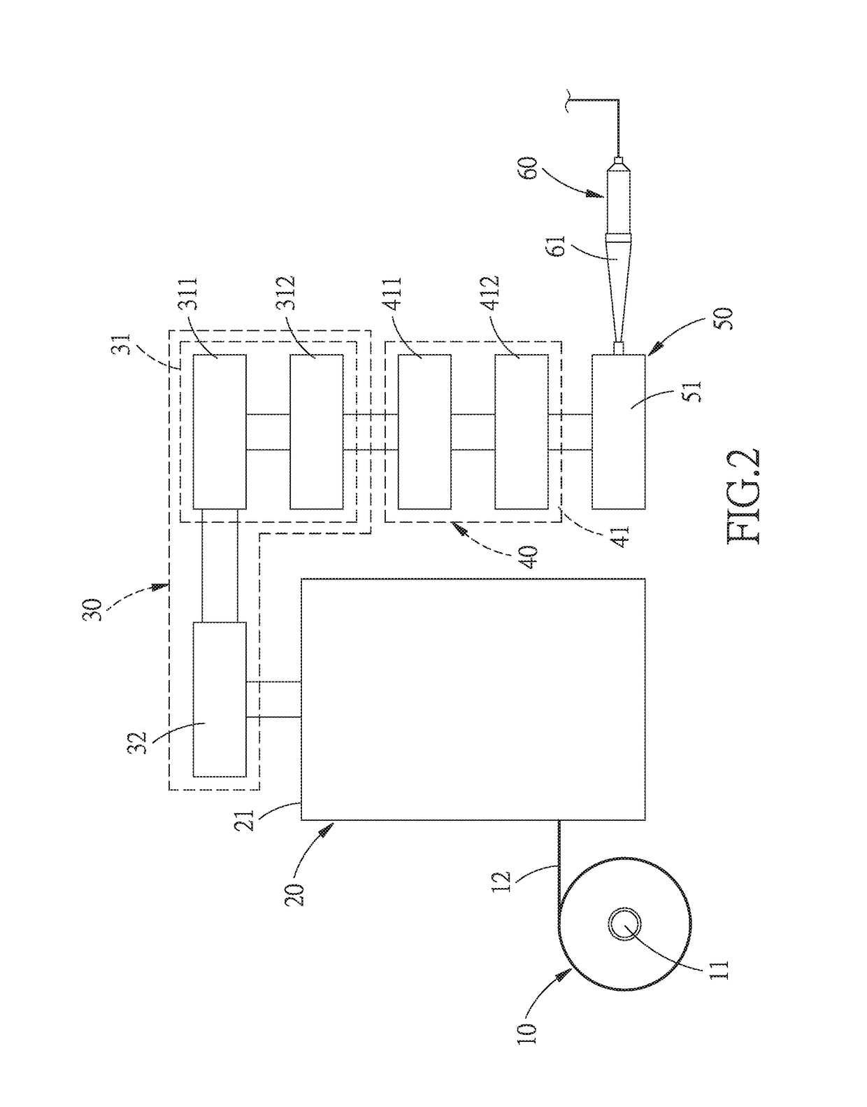
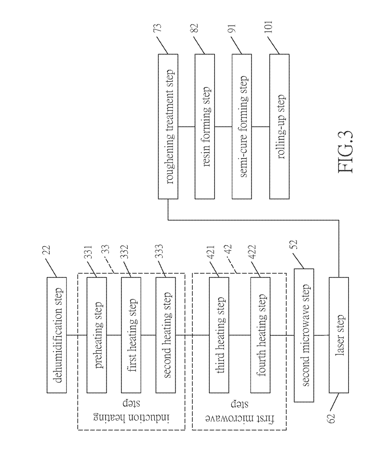
[0031]Referring to FIGS. 1-7, a carbon fiber bundle forming device in accordance with the present invention comprises: a feeding unit 10, a dehumidification unit 20, an induction heating unit 30, a first microwave heating unit 40, a second microwave heating unit 50, a laser unit 60, a roughening treatment unit 70, a resin forming unit 80, a semi-cure forming unit 90, and a rolling-up unit 100.

[0032]The feeding unit 10 includes a carbon-fiber-bundle-raw-material wheel 11 which provides at least one carbon fiber bundle 12.

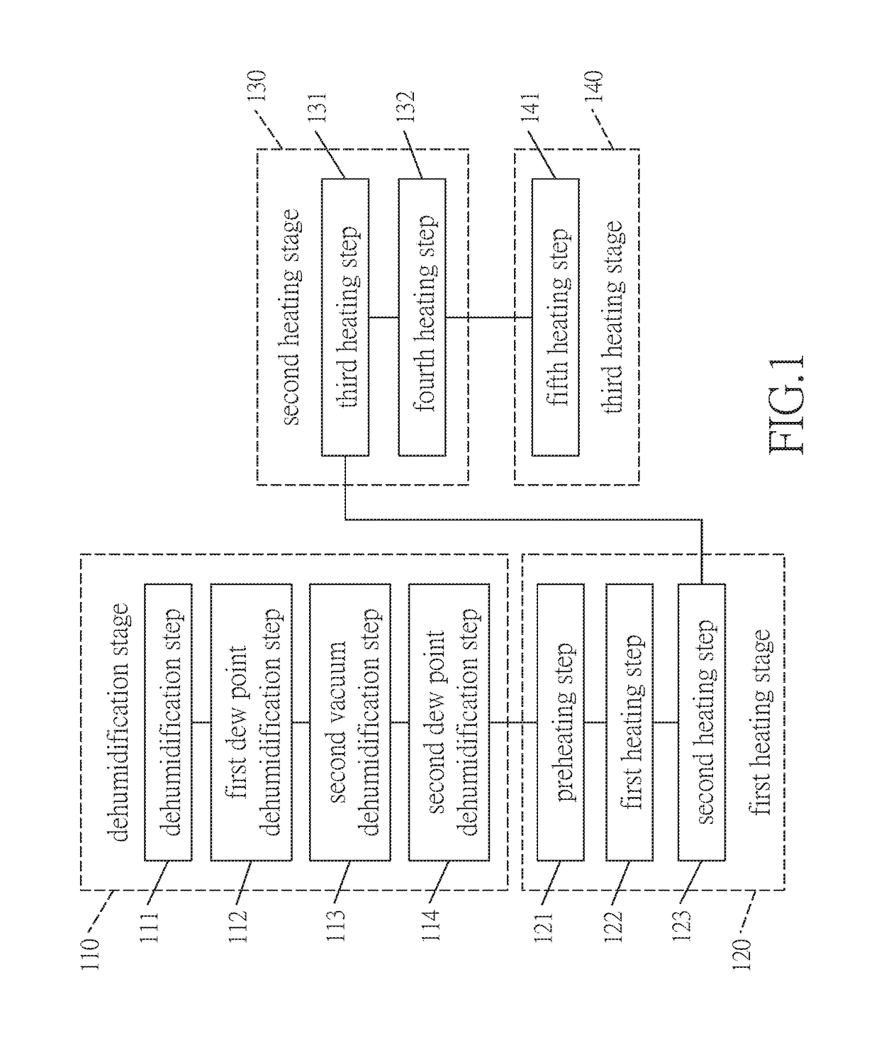
[0033]The dehumidification unit 20 is connected to the feeding unit 10, and includes a dehumidification room 21. The at least one carbon fiber bundle 12 is fully dried after passing through the dehumidification room 21.

[0034]The i...


PUM

PropertyMeasurementUnit
Temperatureaaaaaaaaaa

Abstract

A carbon fiber bundle forming method, wherein the at least one carbon fiber bundle can be evenly heated since it is heated with microwave in the first and second microwave steps. Besides, the at least one carbon fiber bundle is treated in the laser step, laser can reach into the interior of the at least one carbon fiber bundle to enable the carbonization and graphitization to take place more evenly, then the carbon fiber bundle is treated in the subsequent roughening treatment step, the resin forming step and the semi-cure forming step, so that the interior of the at least one carbon fiber bundle can be heated evenly, which allows the at least one carbon fiber bundle to be carbonized evenly.

Description

BACKGROUNDField of the Invention[0001]The present invention relates to a carbon fiber, and more particularly to a carbon fiber forming device and a carbon fiber forming method.Related Prior Art[0002]A conventional carbon fiber bundle forming method is firstly to squeeze the raw material into filaments which are then carbonized, as shown in FIG. 1, and includes the following processes: the carbonized carbon fiber bundle should firstly go through a dehumidification stage 110 which includes: a first vacuum dehumidification step 111, a first dew point dehumidification step 112, a second vacuum dehumidification step 113 and a second dew point dehumidification step 114. With the dehumidification stage 110, moisture can be removed to dry the carbon fiber bundle.[0003]Then, the dried carbon fiber bundle goes through a first heating stage 120 which can be electric resistance heating or gas heating and includes: a preheating step 121, a first heating step 122, and a second heating step 123. T...

Claims


Application Information

Patent Timeline
IPC IPC(8): D02G3/40B29B15/12B29C47/00B29C70/50C08J5/24D01F9/12
CPCD02G3/40B29B15/12B29C70/50C08J5/24D01F9/12B65H54/02B29C48/022D06M15/55C03B37/14C03B37/028D10B2505/02B29C48/05D06M15/17B29B15/122D01F9/32C08J2300/24B29K2105/10B29K2105/106B29C48/156B29C48/28B29C48/287B29C48/2883B29C48/2886C08J5/248
Inventor ONG, CHING-LONG
Owner ONG CHING LONG
Why Eureka
Try Eureka