
Systems and methods for battery micro-short estimation

a technology of system and method, applied in secondary cell servicing/maintenance, instruments, electrochemical generators, etc., can solve the problems of increasing the risk of battery problems during operation, unable to yield the desired amount of accuracy, and degrading the laminated layer of the battery, so as to simplify the structure and procedure, the effect of more accurate detection of micro-shorts

Active Publication Date: 2019-02-14
TOYOTA JIDOSHA KK
View PDF3 Cites 1 Cited by
  • Summary
  • Abstract
  • Description
  • Claims
  • Application Information

AI Technical Summary

Benefits of technology

The present invention provides a system and method to accurately detect battery malfunctions caused by micro-shorts in the separation membrane of a battery. The system includes temperature and impedance sensors to measure the battery's condition, and a controller to determine a threshold impedance associated with the membrane based on its initial impedance and temperature, and prevent current flow when the actual impedance is below the threshold. This system can improve battery safety and life by detecting and stopping battery malfunctions in a timely manner. The method involves monitoring the battery's impedance and temperature in real-time during operation, enabling accurate detection of battery malfunctions and preventing unsafe battery operation.

Problems solved by technology

However, during the lifetime of a battery the charging and discharging procedures may lead to a degradation of the laminated layers of the battery.
The degradation can lead to internal micro-short circuits of battery, which in turn increases the risk of problems with the battery during operation (e.g., thermal runaway).
Therefore, state of charge (SOC), type of deterioration of the battery, and temperature have an impact on the values and the technique of US 2001 / 0028238 may not yield results with a desired amount of accuracy.

Method used


Image

  • Systems and methods for battery micro-short estimation
  • Systems and methods for battery micro-short estimation
  • Systems and methods for battery micro-short estimation

Examples


Embodiment Construction

[0042]Reference will now be made in detail to the present exemplary embodiments of the disclosure, examples of which are illustrated in the accompanying drawings. Wherever possible, the same reference numbers will be used throughout the drawings to refer to the same or like parts.

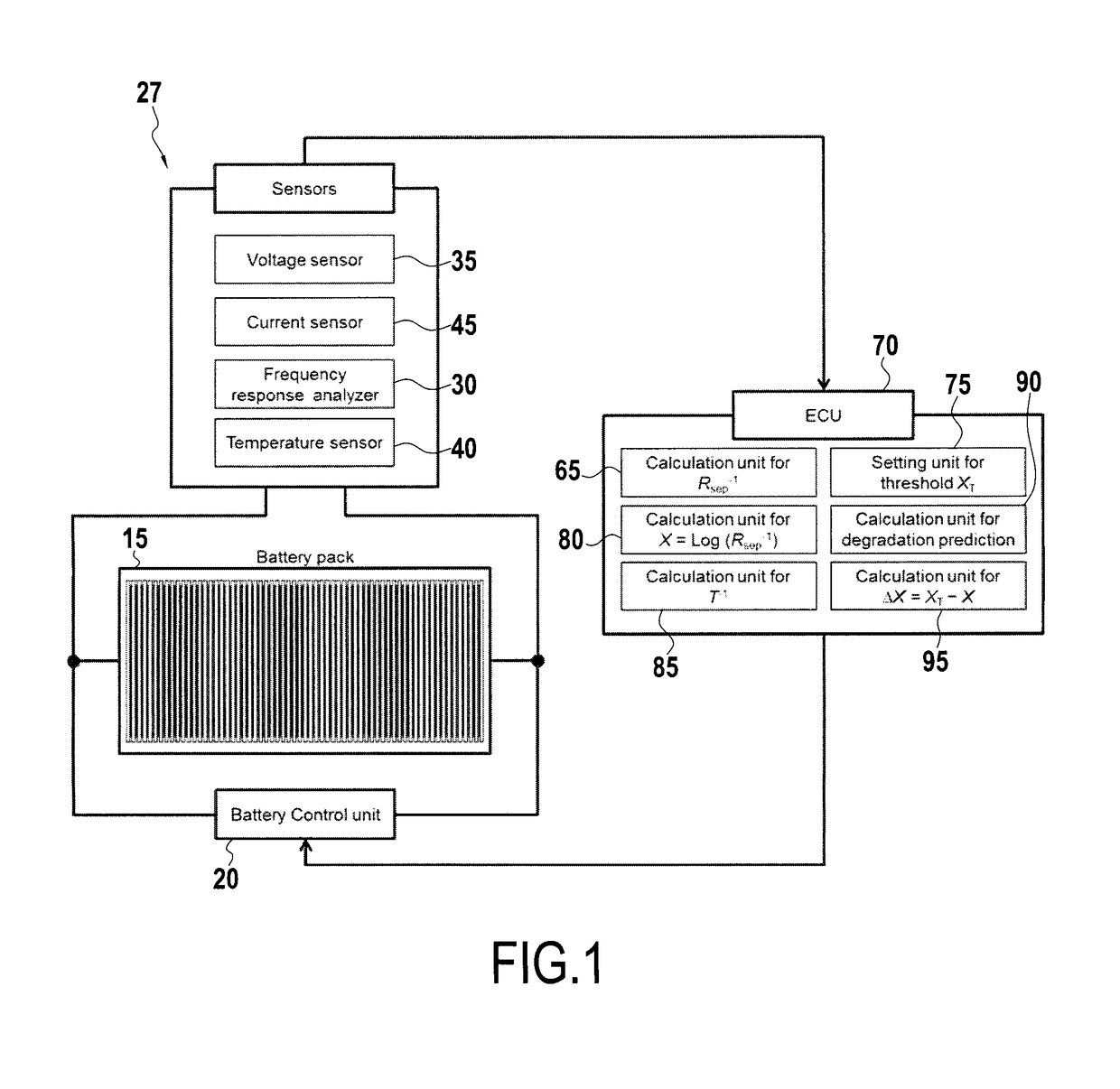
[0043]FIG. 1 is a schematic diagram of a system for monitoring a battery condition according to embodiments of the present disclosure. The system may include a battery pack 15, one or more sensors 27, ECU 70, and a charging control unit 20. Battery pack 15 may include one or more battery cells 10, and a dummy cell (not shown), among others. Battery pack 15 may be any suitable type of battery, for example, a lithium ion battery, a NiMH battery, lead acid battery, etc.

[0044]Battery controller 20 may comprise any suitable battery controller configured to control operational processes of battery pack 15, e.g., charging the battery cells 10, discharging battery cells 10, etc.

[0045]As one of skill in the art unde...


PUM


Abstract

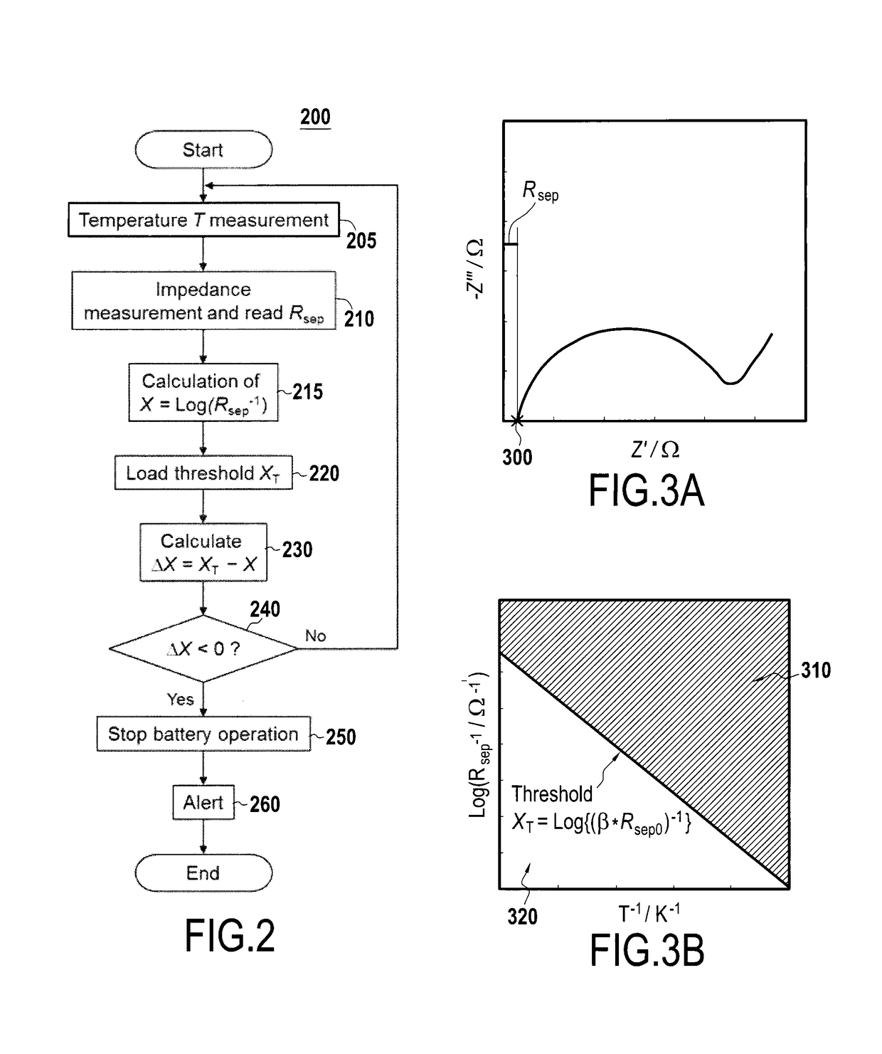
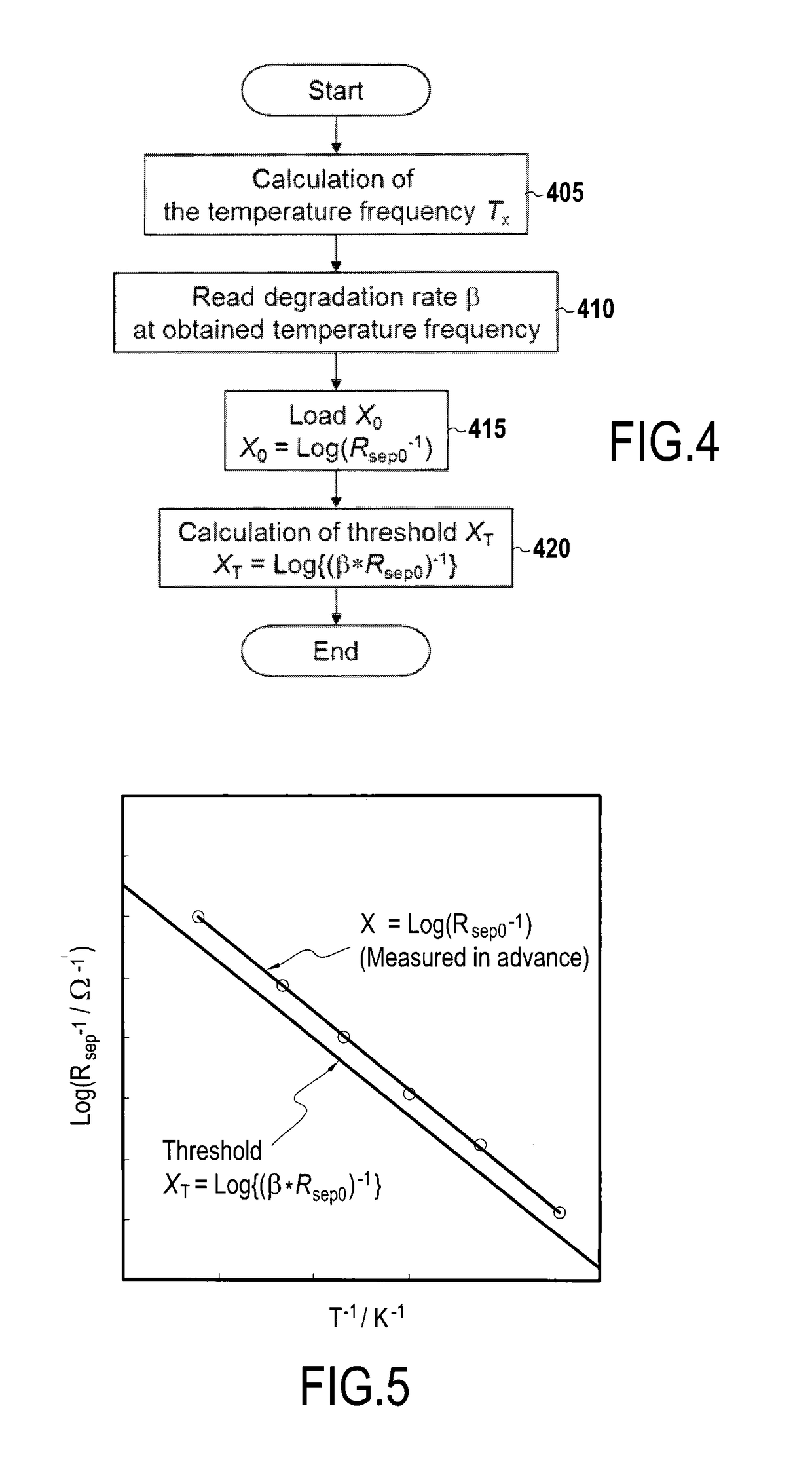
A system for determining a battery condition is provided. The system has temperature sensor configured to provide a temperature value associated with the battery, impedance measuring sensor configured to provide impedance information associated with the battery, and a controller. The controller is configured to determine a threshold impedance associated with a separator membrane of the battery based on an initial impedance of the separator membrane as measured by the impedance measuring sensor and a battery temperature as measured by the temperature sensing means, monitor, during operation of the battery, an actual impedance associated with the separator membrane of the battery based on the impedance information and the battery temperature, permit current flow to and from the battery when actual impedance is greater than the threshold impedance, and prevent current flow to and from the battery when the actual impedance is less than or equal to the threshold impedance.

Description

FIELD OF THE DISCLOSURE[0001]The present disclosure is related to systems and methods for determination of whether to allow operation of, i.e., current flow to and from, a battery. More particularly, the present disclosure is related to determination of a micro-short circuit in a battery that may require stopping of battery operation.BACKGROUND OF THE DISCLOSURE[0002]Rechargeable batteries, also called secondary cells, have become increasingly important as energy stores, in particular for vehicles. Such vehicles may be hybrid vehicles comprising an internal combustion engine and one or more electric motors or purely electrically driven vehicles.[0003]A suitable rechargeable battery for such a vehicle may be a solid-state bipolar battery or other, e.g. liquid type batteries, in particular a laminated Li-ion battery. The rechargeable battery may be realized by a single cell or it may include a set of identical cells. In the latter case the battery is also called a battery pack.[0004]A...

Claims


Application Information

Patent Timeline
IPC IPC(8): G01R31/36H02J7/00H01M10/44H01M10/48H01M10/0525H01M10/42
CPCH02J7/0026H01M2010/4271H01M10/486G01R31/389H01M10/425H01M10/443G01R31/392H01M10/0525G01R31/382G01R31/3842G01R31/396Y02E60/10
Inventor KATOH, YUKIKOMIYAMA, KEITA
Owner TOYOTA JIDOSHA KK
Learn More