
Control device and control method of rotary electric machine

Active Publication Date: 2019-02-14
HONDA MOTOR CO LTD
View PDF0 Cites 0 Cited by
  • Summary
  • Abstract
  • Description
  • Claims
  • Application Information

AI Technical Summary

Benefits of technology

The present invention provides a control device and method for a rotary electric machine that can perform finely tuned rotation control based on positional accuracy. This is achieved by determining the amount of modulation based on the combination of the interpolation angle and the rotational speed, and generating a second driving waveform by performing pulse modulation by this amount of modulation. This allows for flexibility in control design without the need for expensive device configurations. Overall, the control device and method improve the controllability of the rotary electric machine and enhance its performance.

Problems solved by technology

However, with the device proposed in Japanese Patent No. 5502605, an interpolation method “for very-low-speed condition” or “for normal condition” is substantially selected depending on the rotational speed of the motor, and thus it may be difficult to perform rotation control for the purpose of ensuring higher positional accuracy.

Method used


Image

  • Control device and control method of rotary electric machine
  • Control device and control method of rotary electric machine
  • Control device and control method of rotary electric machine

Examples


Embodiment Construction

[0025]Hereinafter, a preferred embodiment of a control device of a rotary electric machine according to the present invention will be described with reference to the attached drawings in connection with a control method of the rotary electric machine.

[Application Example of Motor Control Device 18]

10>

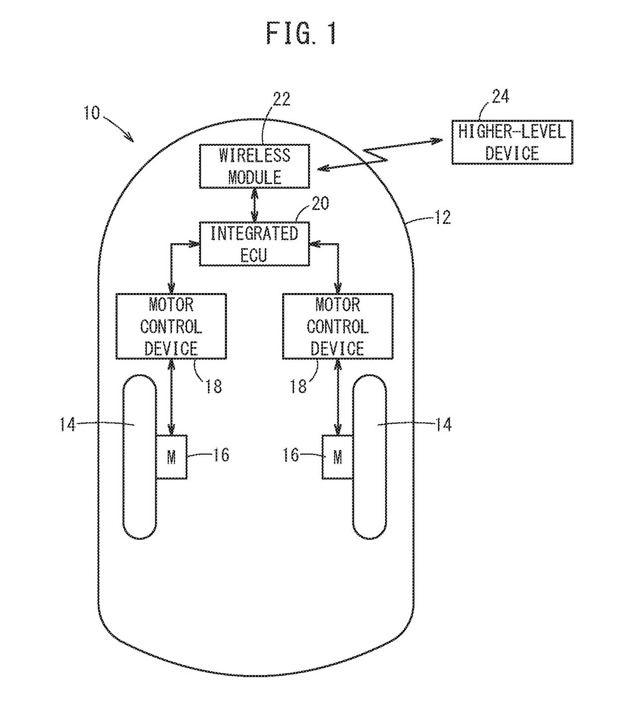
[0026]FIG. 1 is a schematic plan view of an automated guided vehicle 10 into which a control device (here, a motor control device 18) of a rotary electric machine according to an embodiment of the present invention is incorporated. The automated guided vehicle 10 is an unmanned conveyance carrier (an automated guided vehicle), and supplies and conveys various items in a factory, including parts, products in process, or finished products.

[0027]Specifically, this automated guided vehicle 10 is configured to include a vehicle body 12, right and left wheels 14 and 14, right and left motors 16 and 16 (rotary electric machines), right and left motor control devices 18 and 18, an integrated el...


PUM


Abstract

A motor control device performs rotation control of a motor by supplying a first driving waveform and a second driving waveform respectively to a pair of switching elements which make up part of upper and lower arms in an inverter circuit. The motor control device determines the amount of modulation of the second driving waveform from a combination of the calculated interpolation angle and the rotational speed of the motor. The motor control device generates the first driving waveform having a rectangular shape, and further generates the second driving waveform by performing pulse modulation by the determined amount of modulation.

Description

CROSS-REFERENCE TO RELATED APPLICATION[0001]This application is based upon and claims the benefit of priority from Japanese Patent Application No. 2017-155230 filed on Aug. 10, 2017, the contents of which are incorporated herein by reference.BACKGROUND OF THE INVENTIONField of the Invention[0002]The present invention relates to a control device and a control method for performing rotation control of a rotary electric machine.Description of the Related Art[0003]Heretofore, a control device that performs rotation control of a rotary electric machine including a motor has been known. For example, various techniques for suppressing generation of an inrush current or torque ripple in a low-speed rotation region have been proposed.[0004]In Japanese Patent No. 5502605, a control device that makes up for a deficiency of angular resolution due to the number of Hall sensors by interpolating the positions of magnetic poles (that is, the angle of rotation) of a rotor when performing rotation co...

Claims


Application Information

Patent Timeline
IPC IPC(8): H02P6/16B60L15/20H02P6/28B60L3/00
CPCH02P6/16B60L15/20H02P6/28B60L3/0061H02P6/10H02P27/085H02P6/08H02P6/153B60L15/06B60L2200/40B60L2240/421B60L2260/32Y02P90/60Y02T10/72Y02T10/64
Inventor YAJIMA, SHIGEOTANAKA, MAKOTO
Owner HONDA MOTOR CO LTD
Features
  • Generate Ideas
  • Intellectual Property
  • Life Sciences
  • Materials
  • Tech Scout
  • Unparalleled Data Quality
  • Higher Quality Content
  • 60% Fewer Hallucinations
Learn More