
Apparatus and method for filter bank multi-carrier signal modulation with low papr in multiple antenna system

a multi-carrier and signal modulation technology, applied in the field of transmission and reception techniques using a filter bank multi-carrier method, can solve the problems of difficult application of alamouti codes to the fbmc modulation technique and inability to obtain single carrier effects

Active Publication Date: 2019-02-14
RES COOPERATION FOUND OF YEUNGNAM UNIV
View PDF0 Cites 6 Cited by
  • Summary
  • Abstract
  • Description
  • Claims
  • Application Information

AI Technical Summary

Benefits of technology

The present patent is about a method for generating a transmission signal in a multiple antenna system with low peak-to-average power ratio. The method involves using a discrete Fourier transform to generate two groups of symbols, and then extracting real and imaginary parts from these symbols. A phase shift is then applied to one of the groups of symbols to generate a transmission signal. The method can be used in a filter bank multi-carrier system and can provide a more efficient way to generate a transmission signal with low peak power.

Problems solved by technology

Particularly, in an FBMC modulation technique and an offset quadrature amplitude modulation (OQAM) technique, there is a problem in that a single carrier effect cannot be obtained due to a structural problem of OQAM even when discrete Fourier transform (DFT) spreading is applied as in a single carrier-frequency division multi access (SC-FDMA) technique.
Meanwhile, unlike an orthogonal frequency division multiplexing (OFDM) technique, it has been difficult to apply an Alamouti code to the FBMC modulation technique due to inherent inter-carrier interference (ICI) between antennas.

Method used


Image

  • Apparatus and method for filter bank multi-carrier signal modulation with low papr in multiple antenna system
  • Apparatus and method for filter bank multi-carrier signal modulation with low papr in multiple antenna system
  • Apparatus and method for filter bank multi-carrier signal modulation with low papr in multiple antenna system

Examples


first embodiment

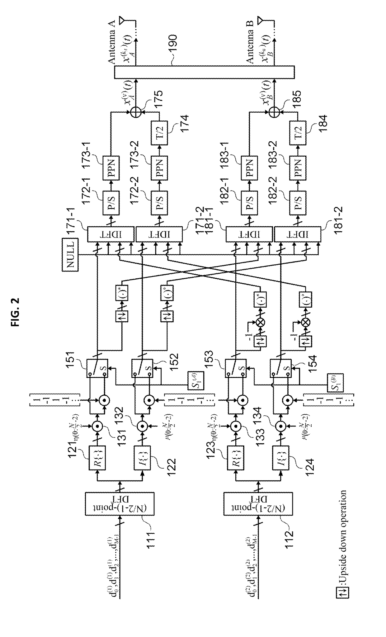
[0019]FIG. 2 is a detailed configuration diagram of a modulation apparatus according to the present disclosure.

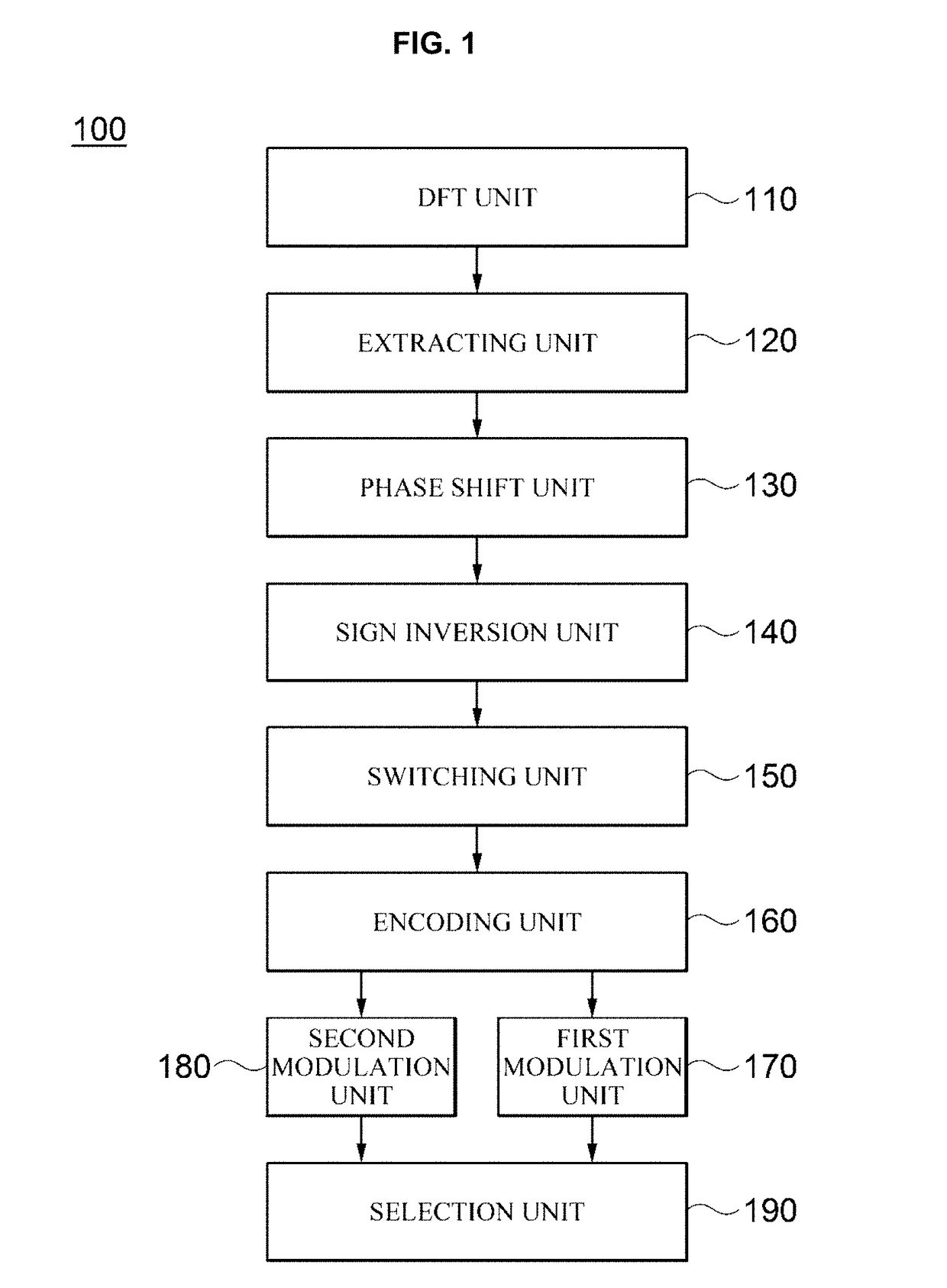
[0020]Referring to FIG. 2, a DFT unit 110 performs (N / 2−1)-point DFTs 111 and 112 on two quadrature amplitude modulation (QAM) data symbol groups including N / 2−1 mth QAM data symbols which are input in parallel.

[0021]Specifically, in the example shown in FIG. 2, a QAM data symbol dk,m(1) which is input to an upper DFT 111 and a QAM data symbol dk,m(2) which is input to a lower DFT 112 may be expressed by the following equations, Equations 1 and 2, respectively.

dk,m(1)=ak,m(1)+jbk,m(1),0≤k≤N / 2−2,0≤m≤M−1  [Equation 1]

dk,m(2)=ak,m(2)+jbk,m(2),0≤k≤N / 2−2,0≤m≤M−1  [Equation 2]

[0022]In Equations 1 and 2, ak,m(1) denotes a real part symbol of dk,m(1), bk,m(1) denotes an imaginary part symbol of dk,m(1), ak,m(2) denotes a real part symbol of dk,m(2), bk,m(2) denotes an imaginary part symbol of dk,m(2), N denotes the number of subcarriers, and M denotes a length of a data frame. Thes...

second embodiment

[0063]FIG. 4 is a detailed configuration diagram of a modulation apparatus according to the present disclosure.

[0064]By comparing FIGS. 2 and 4, the embodiment shown in FIG. 4 has the same structure as the embodiment shown in FIG. 2 except that switches 176 and 186 for selecting an output to be time-shifted by T / 2 from among outputs of the upper PPNs 173-1 and 183-1 and outputs of the lower PPNs 173-2 and 183-2 are respectively added to the first modulation unit 170 and the second modulation unit 180.

[0065]However, unlike in the embodiment shown in FIG. 2, in the embodiment shown in FIG. 4, a transmission candidate signal for each antenna may be additionally generated by a switching operation of each of the switches 176 and 186 added to the first modulation unit 170 and the second modulation unit 180.

[0066]Specifically, in the example shown in FIG. 4, the two switches 176 and 186 operate in synchronization with a switching control bit S2. When the switching control bit S2 is 0, the ...

third embodiment

[0079]FIG. 5 is a detailed configuration diagram of a modulation apparatus according to the present disclosure.

[0080]In the embodiment shown in FIG. 5, QAM data symbols of one frame, which are input to an upper DFT 111 and a lower DFT 112 of a DFT unit 110, are divided into a plurality of consecutive data blocks, and then a plurality of transmission candidate signal sets are generated for each data block to select a transmission candidate signal set having the lowest peak power or the lowest PAPR as a transmission candidate set for each data block.

[0081]Specifically in the example shown in FIG. 5, a QAM data symbol dk,m(1) of an lth data block, which is input to the upper DFT 111, and a QAM data symbol dk,m(2) of the lth data block, which is input to the lower DFT 112, may be respectively expressed by the following equations, Equations 35 and 36.

dk,m(1)=ak,m(1)jbk,m(1),0≤n≤N / 2−2,lW≤m≤(l+1)W−1  [Equation 35]

dk,m(2)=ak,m(2)jbk,m(2),0≤n≤N / 2−2,lW≤m≤(l+1)W−1  [Equation 36]

[0082]In this c...


PUM


Abstract

An apparatus and method for filter bank multi-carrier signal modulation with a low peak-to-average power ratio (PAPR) in a multiple antenna system are disclosed. According to embodiments of the present disclosure, in a multiple antenna transmission method, after a plurality of transmission candidate signals, which are modulated for each antenna using discrete Fourier transform (DFT) spread filter bank multi-carrier and offset quadrature amplitude modulation (FBMC / OQAM) techniques and are capable of obtaining a single carrier effect, are generated, a transmission candidate signal with a low PAPR can be selected and transmitted, and thus peak-to-average power ratio performance can be effectively improved, and interference between subcarriers can be eliminated by applying an Alamouti coding manner.

Description

CROSS-REFERENCE TO RELATED APPLICATION[0001]This application claims the benefit under 35 USC § 119(a) of Korean Patent Application No. 10-2017-0102619, filed on Aug. 11, 2017, in the Korean Intellectual Property Office, the entire disclosure of which is incorporated herein by reference for all purposes.BACKGROUND1. Field[0002]The present disclosure relates to a transmission and reception technique using a filter bank multi-carrier method, and more specifically, to filter bank multi-carrier and offset quadrature amplitude modulation (FBMC / OQAM) techniques using discrete Fourier transform (DFT) spreading.2. Discussion of Related Art[0003]A filter bank multi-carrier (FBMC) modulation technique using a plurality of subcarriers has entered the spotlight as a modulation technique for fifth-generation (5G) wireless communication. However, in the FBMC modulation technique, a high peak-to-average power ratio (PAPR) characteristic is exhibited due to overlapping of a plurality of subcarrier s...

Claims


Application Information

Patent Timeline
Patent Type & Authority Applications(United States)
IPC IPC(8): H04L27/26H04B1/707H04L27/34
CPCH04L27/264H04B1/707H04L27/34H04L27/2614H04L27/2636H04L27/2698H04L27/26416H04L1/0668H04L27/2621
Inventor CHOI, KWONHUENA, DONGJUN
Owner RES COOPERATION FOUND OF YEUNGNAM UNIV
Learn More