Apparatus for physical simulation experiment for fracturing in horizontal well layer by layer by spiral perforation and method thereof

Active Publication Date: 2019-02-21
CHINA UNIV OF PETROLEUM (BEIJING)
View PDF0 Cites 2 Cited by
  • Summary
  • Abstract
  • Description
  • Claims
  • Application Information

AI Technical Summary

Benefits of technology

[0036]Compared with the prior arts, the apparatus and method provided in the invention has following advantages: (1) kinds of multistage fracture could be realized when no leakage of pressure at the mouth of well; (2) different stratum could be opened by spiral perforations t

Problems solved by technology

Unconventional oil and gas reservoirs, such as shale oil and gas, coal gas and tight oil an

Method used


Image

  • Apparatus for physical simulation experiment for fracturing in horizontal well layer by layer by spiral perforation and method thereof
  • Apparatus for physical simulation experiment for fracturing in horizontal well layer by layer by spiral perforation and method thereof
  • Apparatus for physical simulation experiment for fracturing in horizontal well layer by layer by spiral perforation and method thereof

Examples


embodiment 1

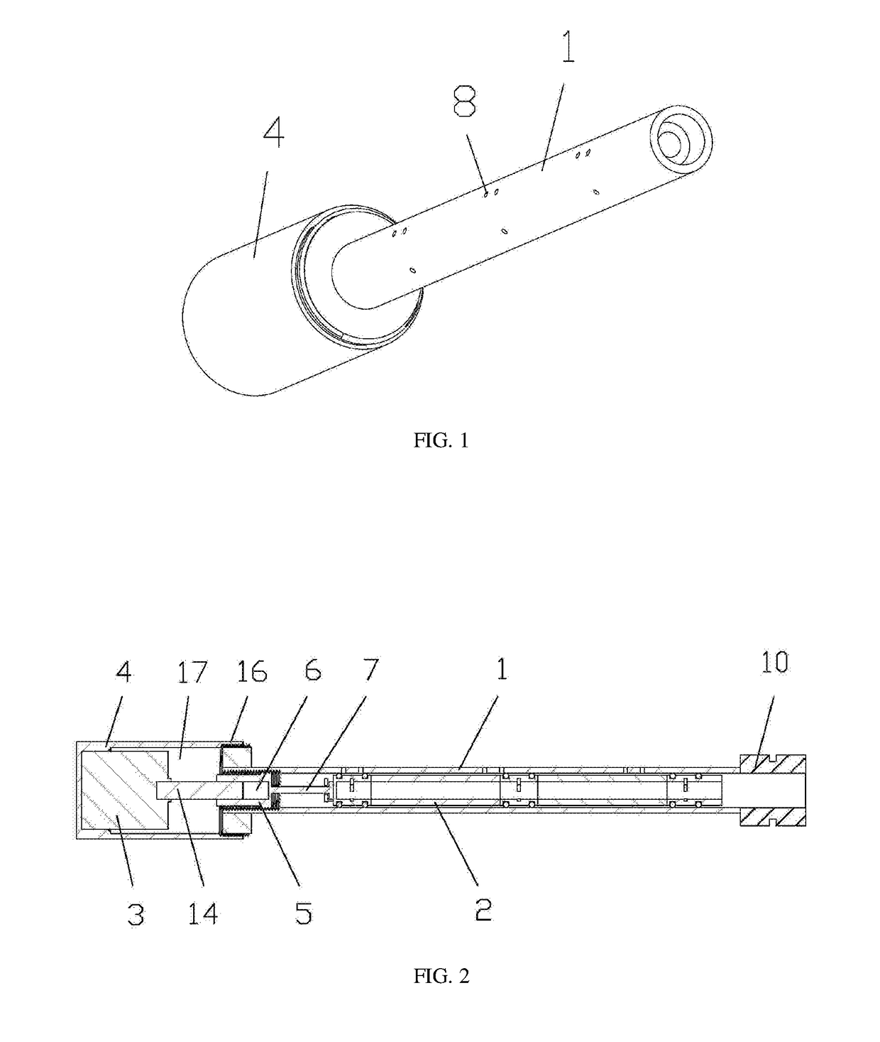
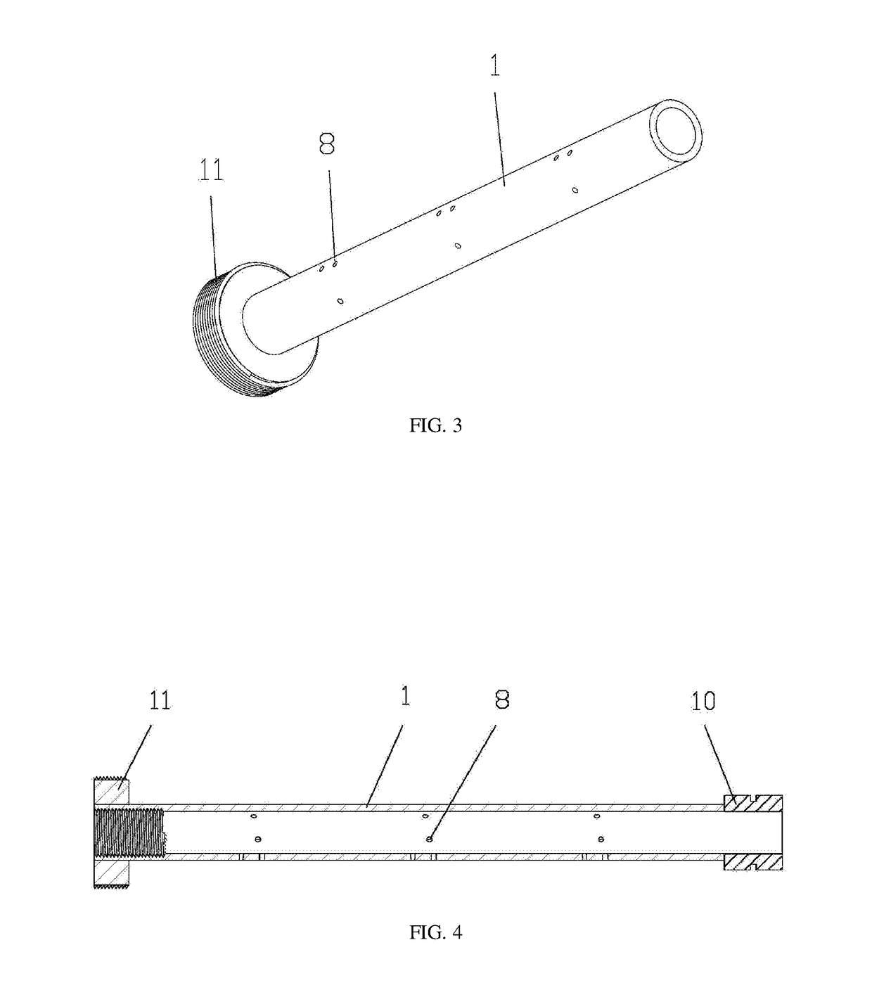
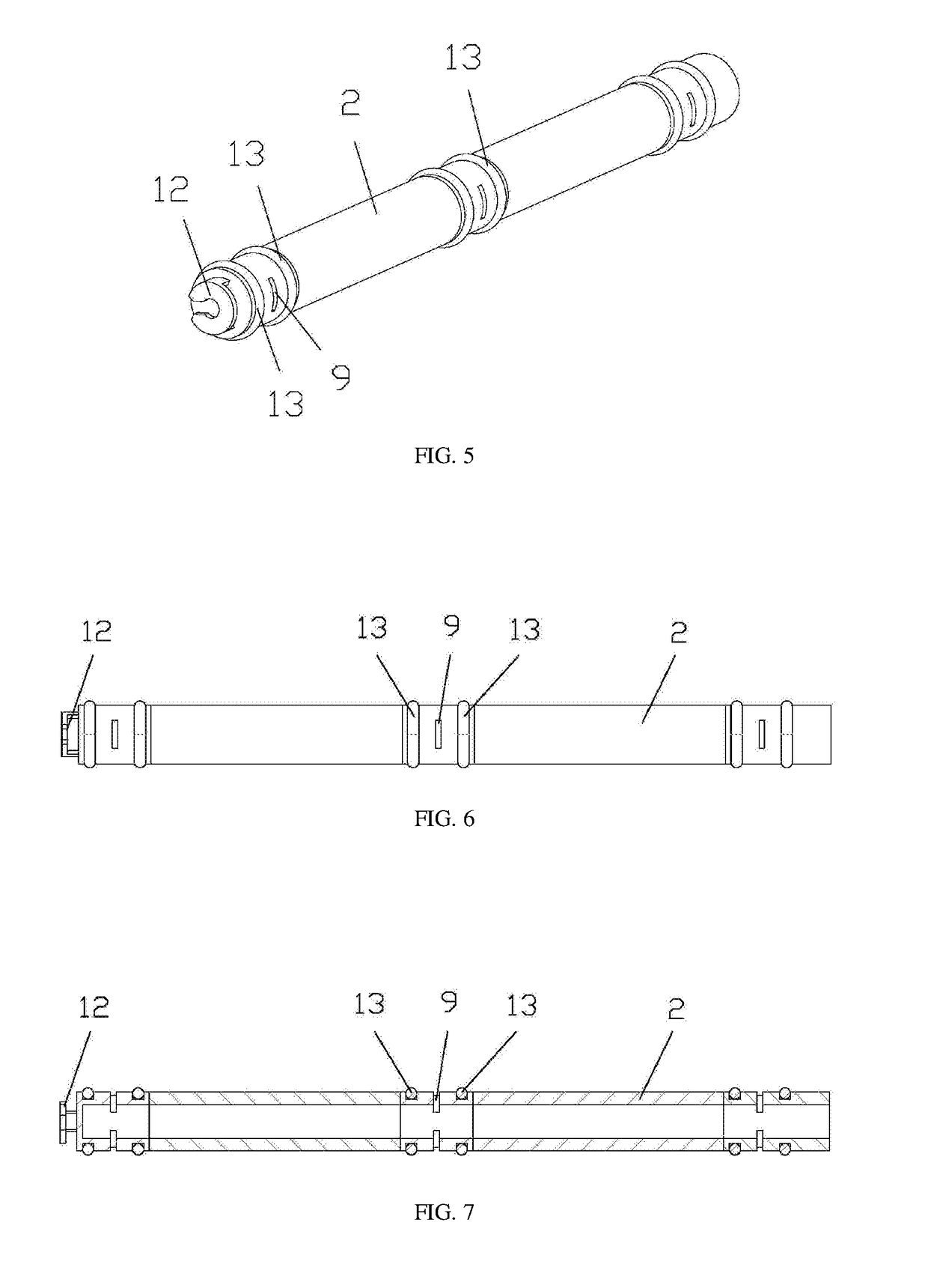
[0052]In FIGS. 1-13, there is shown apparatus for physical simulation experiment for fracturing in horizontal well layer by layer by spiral perforation. The apparatus comprises an outer wellbore 1 and an inner wellbore 2. The inner wellbore 2 is configured in the outer wellbore 1. The apparatus also comprises an electrical machinery 3, a locating shell 4 and a displacement transducer 5. The electrical machinery 3 is configured in the locating shell 4. One end of the outer wellbore 1 is connected with the locating shell 4. One end of the displacement transducer 5 is connected with the electrical machinery 3. The other end of the displacement transducer 5 is connected with one end of the inner wellbore 2. The outer wellbore 1 is provided with three layers of spiral perforations 8. The inner wellbore 2 is provided with three layers of through-holes 9.

[0053]As best seen in FIG. 12, the displacement transducer 5 is composed of a connecting rod 7, and a D-shaped hollow cavity 6, with a po...

embodiment 2

[0073]Another embodiment of the apparatus and method of this invention is constructed and operates the same as the embodiment 1, the only difference being the design of parameters, and particularly is as follows:

[0074]Two circles of spiral perforations are simulated in the perforation section of each spiral perforation layer of the outer wellbore, and three through-holes are provided on each circle. The diameter of the spiral perforation is 1 mm. The distance “L” between adjacent two spiral perforation layers on the outer wellbore is 40 mm. Two through-holes are provided on each through-hole layer of the inner wellbore, and the two through-holes are evenly provided on the through-hole layer. The height of the through-hole is 1.0 mm.

[0075]“H” refers to distance between outer surfaces of two sealing rings on each through-hole layer in the inner wellbore, and H>h+2a, wherein, “h” refers to height of the perforation section, and h=6 mm; “a” refers to thickness of the sealing ring, and a...

embodiment 3

[0077]Another embodiment of the apparatus and method of this invention is constructed and operates the same as the embodiment 1, the only difference being the design of parameters, and particularly is as follows:

[0078]Three circles of spiral perforations are simulated in the perforation section of each spiral perforation layer of the outer wellbore, and three through-holes are provided on each circle. The diameter of the spiral perforation is 1 mm. The distance “L” between adjacent two spiral perforation layers on the outer wellbore is 50 mm. Two through-holes are provided on each through-hole layer of the inner wellbore, and the two through-holes are evenly provided on the through-hole layer. The height of the through-hole is 1.0 mm.

[0079]“H” refers to distance between outer surfaces of two sealing rings on each through-hole layer in the inner wellbore, and H>h+2a, wherein, “h” refers to height of the perforation section, and h=8 mm; “a” refers to thickness of the sealing ring, and...


PUM


Abstract

Apparatus and method for a physical simulation experiment of fracturing an unconventional oil and gas reservoir layer by layer by spiral perforation via a horizontal well bore. The apparatus includes an outer wellbore provided with at least three layers of spiral perforations, and an inner wellbore provided with at least three layers of through-holes. The method includes injecting fracturing fluid into the inner wellbore, and opening a first layer cracks of a stratum by the fracturing fluid passing the first through-hole layer and the first spiral perforation layer, opening a second layer cracks of the stratum by the fracturing fluid passing second through-hole layer and second spiral perforation layer and opening a third layer cracks of the stratum by the fracturing fluid passing third through-hole layer and third spiral perforation layer.

Description

TECHNICAL FIELD[0001]The present invention relates generally to field of technology for oil and gas development, and more particularly relates to apparatus for physical simulation experiment for fracturing in horizontal well layer by layer by spiral perforation and method thereof.BACKGROUND OF THE INVENTION[0002]Unconventional oil and gas reservoirs, such as shale oil and gas, coal gas and tight oil and gas and so on, are widely distributed in China and prospective reserves thereof are huge. As such high-efficiency exploitation of unconventional oil and gas reservoirs is a long-term focus in the petroleum industry. An unconventional oil and gas reservoir exhibits the feature of low pore and low permeability. Thus, the high-efficiency exploitation of an unconventional oil reservoir needs large-scale hydraulic fracturing operations to form a large number of and even net-like cracks, with high diversion ability in the reservoir, so that migration conditions for oil and gas are improved...

Claims


Application Information

Patent Timeline
IPC IPC(8): E21B47/10
CPCE21B47/10E21B43/26G01N3/36
Inventor HOU, BINGCHANG, ZHIJIN, YANCHEN, MIANLU, YUNHULIN, BOTAOZHOU, ZHOUTAN, PENG
Owner CHINA UNIV OF PETROLEUM (BEIJING)
Why Eureka
Try Eureka