Reducing noise in a capacitive sensor with a pulse density modulator

Active Publication Date: 2019-02-21
CIRRUS LOGIC INC
View PDF30 Cites 1 Cited by
  • Summary
  • Abstract
  • Description
  • Claims
  • Application Information

AI Technical Summary

Benefits of technology

[0005]In accordance with the teachings of the present disclosure, certain disadvantages and problems as

Problems solved by technology
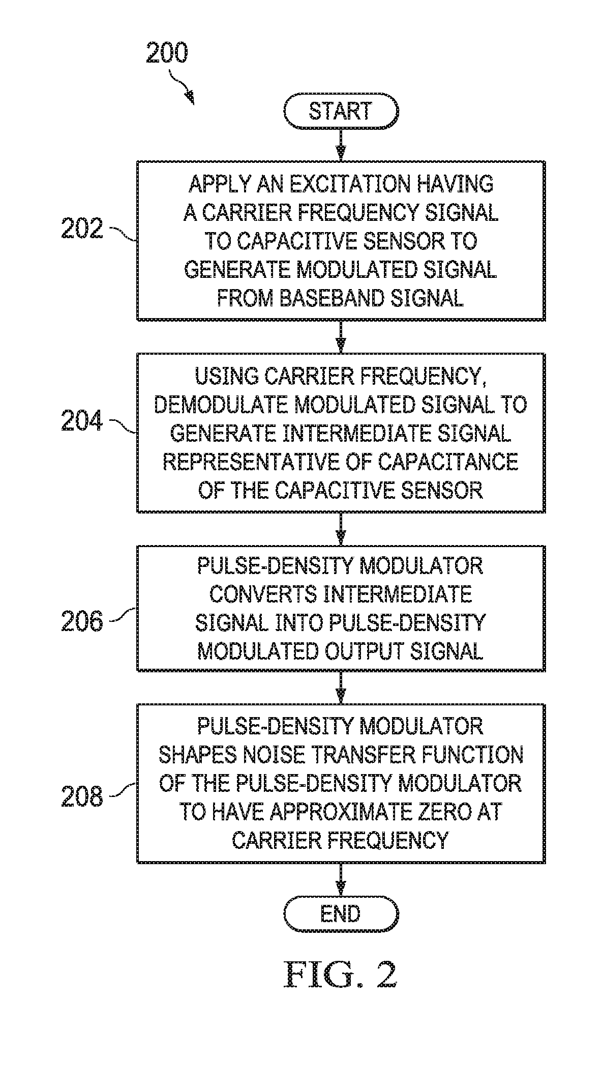
For example, in some applications, an integrated circuit output pin carrying a pulse-density modulated signal representative o

Method used


Image

  • Reducing noise in a capacitive sensor with a pulse density modulator
  • Reducing noise in a capacitive sensor with a pulse density modulator

Examples


Embodiment Construction

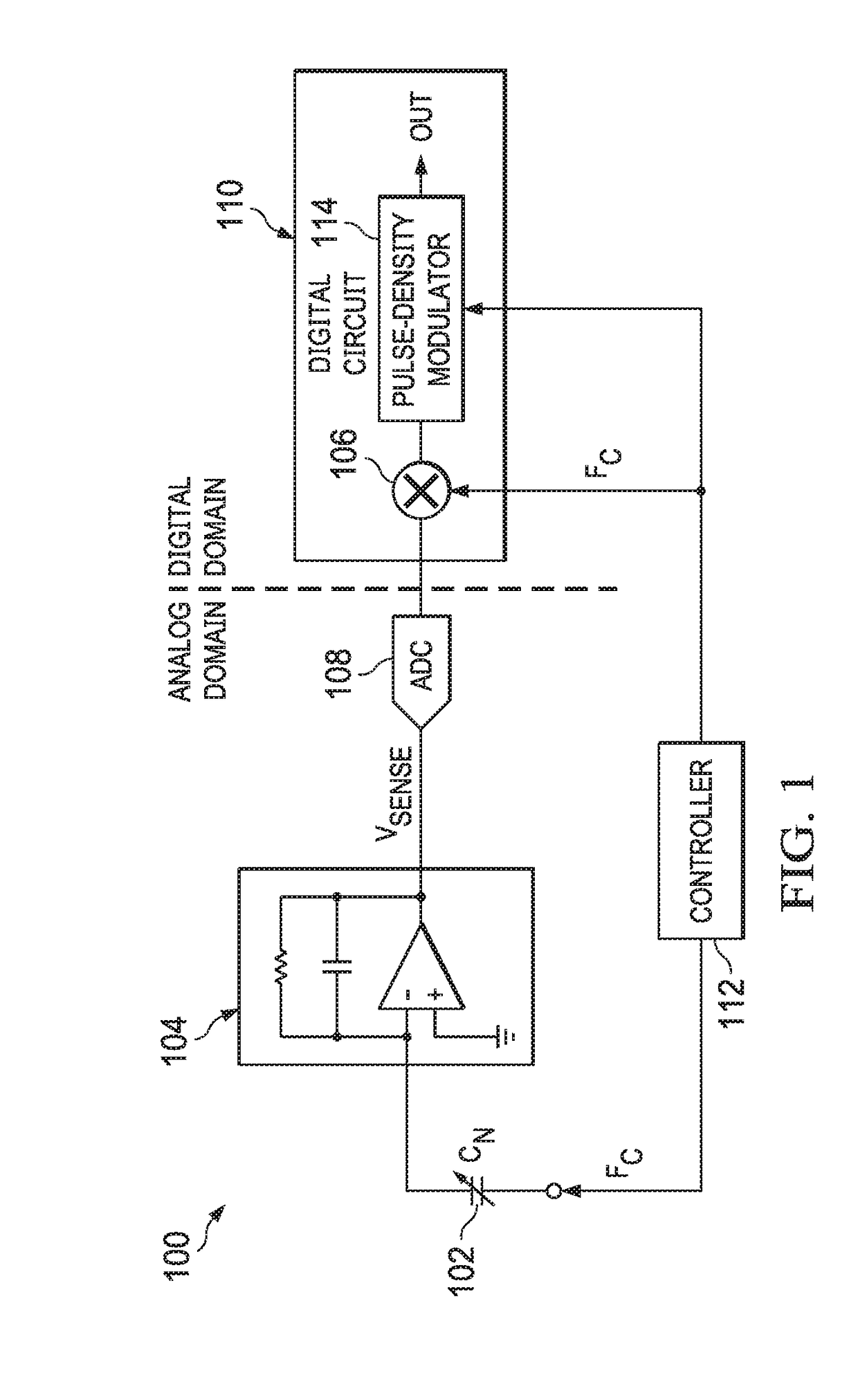
[0013]FIG. 1 is a block diagram of selected components of an example capacitance-sensing circuit 100 for sensing a variable capacitance CM of a component 102, wherein carrier demodulation is implemented in a digital domain, in accordance with embodiments of the present disclosure. In some embodiments, component 102 may comprise an audio speaker and capacitance CM may be representative of a displacement of an audio transducer of such audio speaker. However, the systems and methods disclosed herein are not limited to measuring displacement in an audio speaker, and may be applied to any suitable measuring or sensing of a capacitance.

[0014]As shown in FIG. 1, capacitance sensing circuit 100 may include a capacitance-to-voltage converter (CVC) 104, an analog-to-digital converter (ADC) 108, digital circuitry 110, and a controller 112. CVC 104 may comprise a charge integrator configured to integrate charge at its input to generate a voltage signal VSENSE indicative of capacitance CM of com...


PUM


Abstract

A method for measuring a capacitive sensor output may include applying an excitation signal to a capacitor of the capacitive sensor which causes generation of a modulated signal from a baseband signal, wherein the excitation signal is of a carrier frequency which is higher than frequency content of the baseband signal, demodulating the modulated signal to generate an intermediate signal representative of a capacitance of the capacitor wherein the demodulating is based, at least in part, on the excitation signal, converting the intermediate signal into a pulse-density modulated output signal with a pulse-density modulator, and shaping a noise transfer function of the pulse-density modulator to have an approximate zero at the carrier frequency.

Description

CROSS-REFERENCE AND RELATED APPLICATION[0001]The present disclosure claims benefit of U.S. Provisional Patent Application Ser. No. 62 / 548,197, filed Aug. 21, 2017, which is incorporated by reference herein in its entirety.FIELD OF DISCLOSURE[0002]The present disclosure relates in general to measuring capacitance, and more specifically, to systems and methods for measuring capacitance using a capacitance to voltage converter in a noisy environment.BACKGROUND[0003]In many electrical and electronic systems, it may be desirable to measure a capacitance within a circuit in order to take action responsive to the measured capacitance. For example, a capacitive sensor used in an audio speaker may be used to sense a position of a transducer diaphragm of the audio speaker. The capacitance value of a capacitive sensor which changes responsive to an audio signal driven through the speaker may be measured by driving a carrier tone on one terminal of the speaker and sensing a modulated signal cur...

Claims


Application Information

Patent Timeline
IPC IPC(8): G01R27/26H04R29/00
CPCG01R27/2605H04R29/001H04R3/002
Inventor VELLANKI, AMARYOU, ZHONGGABORIAU, JOHANN G.
Owner CIRRUS LOGIC INC
Why Eureka
Try Eureka