Variable orifice flow control device

a flow control device and variable orifice technology, applied in the field of compressors, to achieve the effect of reducing drag and windage losses

Active Publication Date: 2019-02-28
TRANE INT INC
View PDF5 Cites 0 Cited by
  • Summary
  • Abstract
  • Description
  • Claims
  • Application Information

AI Technical Summary

Benefits of technology

[0003]A flow control device may be disposed between a volute housing of a compressor and a motor housing of the compressor that allows the flow of a fluid from the volute housing into the motor housing to be controlled. This may reduce drag and windage losses while meeting the variable cooling needs of compressor parts such as the motor, shaft and bearings.

Problems solved by technology

However, the flow of compressed gas may cause inefficiency due to drag and windage losses.

Method used


Image

  • Variable orifice flow control device
  • Variable orifice flow control device
  • Variable orifice flow control device

Examples


Embodiment Construction

[0011]A variable flow control device disposed between a volute housing and a compressor motor housing can improve compressor efficiency by metering the amount of coolant provided based on compressor motor needs, and thus reducing drag and windage losses while meeting compressor cooling needs.

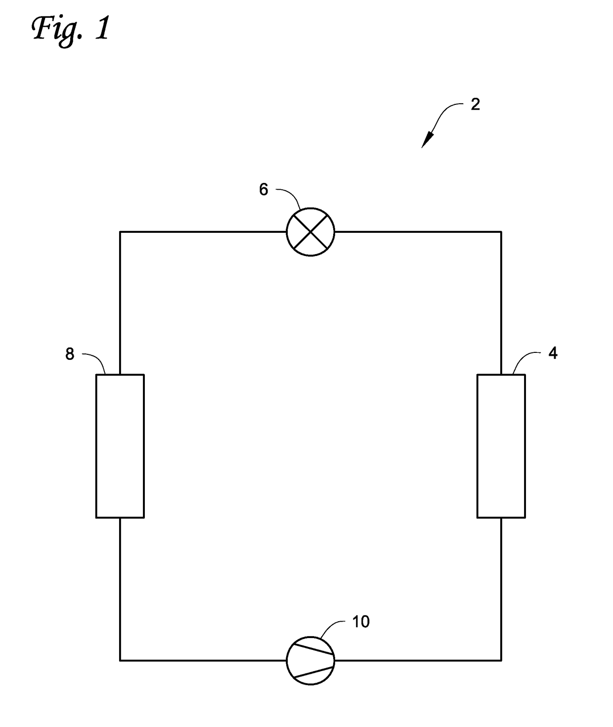
[0012]FIG. 1 is a schematic diagram of a refrigerant circuit 2, according to an embodiment. The refrigerant circuit 2 generally includes a compressor 10, a condenser 4, an expansion device 6, and an evaporator 8. The compressor 10 can be a positive displacement compressor, for example, a centrifugal compressor. The refrigerant circuit 2 is an example and can be modified to include additional components. For example, in an embodiment, the refrigerant circuit 2 can include other components such as, but not limited to, an economizer heat exchanger, one or more flow control devices, a receiver tank, a dryer, a suction-liquid heat exchanger, or the like.

[0013]The refrigerant circuit 2 can generally b...


PUM


Abstract

A variable orifice flow device controls the flow of a fluid between a volute casing and a compressor motor casing in a compressor. The variable orifice flow device may be a shuttling valve, with positions controlled by, for example, valves controlling the flow of the fluid into a space opposite a side within the shuttling valve assembly. The variable orifice flow device may have one or more orifices through which a fluid can enter the compressor motor casing, and the surface area of the orifices may be controlled by the position of the shuttling valve.

Description

FIELD[0001]This disclosure relates to a compressor, particularly valves used in controlling flow of cooling gas within the compressor.BACKGROUND[0002]Compressor parts, particularly the motor, shaft, and bearings such as magnetic bearings require cooling while the compressor is in operation. The cooling may be provided, for example, by a flow of compressed gas discharged from the compressor. However, the flow of compressed gas may cause inefficiency due to drag and windage losses. The cooling demands of the compressor parts may vary with the speed of operation of the compressor and the pressure it produces at its discharge. Current systems use fixed-size holes to allow compressed gas to enter a casing of a motor of the compressor to cool compressor components.BRIEF SUMMARY[0003]A flow control device may be disposed between a volute housing of a compressor and a motor housing of the compressor that allows the flow of a fluid from the volute housing into the motor housing to be control...

Claims


Application Information

Patent Timeline
Patent Type & Authority Applications(United States)
IPC IPC(8): F16K11/07F16K31/06F25B31/00F25B41/04
CPCF16K11/0712F25B41/04F25B31/006F16K31/0675F16K31/124F16K31/42F16K3/24F16K3/26Y10T137/6579F16K31/1221F16K3/265F16K1/126F16K1/123F05D2260/211F01D25/125F05D2260/205
Inventor ESPELIEN, CHRISTOPHER
Owner TRANE INT INC
Why Eureka
Try Eureka