Method of configuring a test device designed to test an electronic control unit, and a configuration system

Active Publication Date: 2019-02-28
DSPACE DIGITAL SIGNAL PROCESSING & CONTROL ENG
View PDF0 Cites 2 Cited by
  • Summary
  • Abstract
  • Description
  • Claims
  • Application Information

AI Technical Summary

Benefits of technology

[0012]It is therefore an object of the present invention to further develop the configuration process of HIL and RCP

Problems solved by technology

The development of control units has become a highly complex process.
The known configuration systems or configuration diagrams have the disadvantage that the configuration of the test device properties in certain application scenarios is time-consuming, unclear an

Method used


Image

  • Method of configuring a test device designed to test an electronic control unit, and a configuration system
  • Method of configuring a test device designed to test an electronic control unit, and a configuration system
  • Method of configuring a test device designed to test an electronic control unit, and a configuration system

Examples


Example

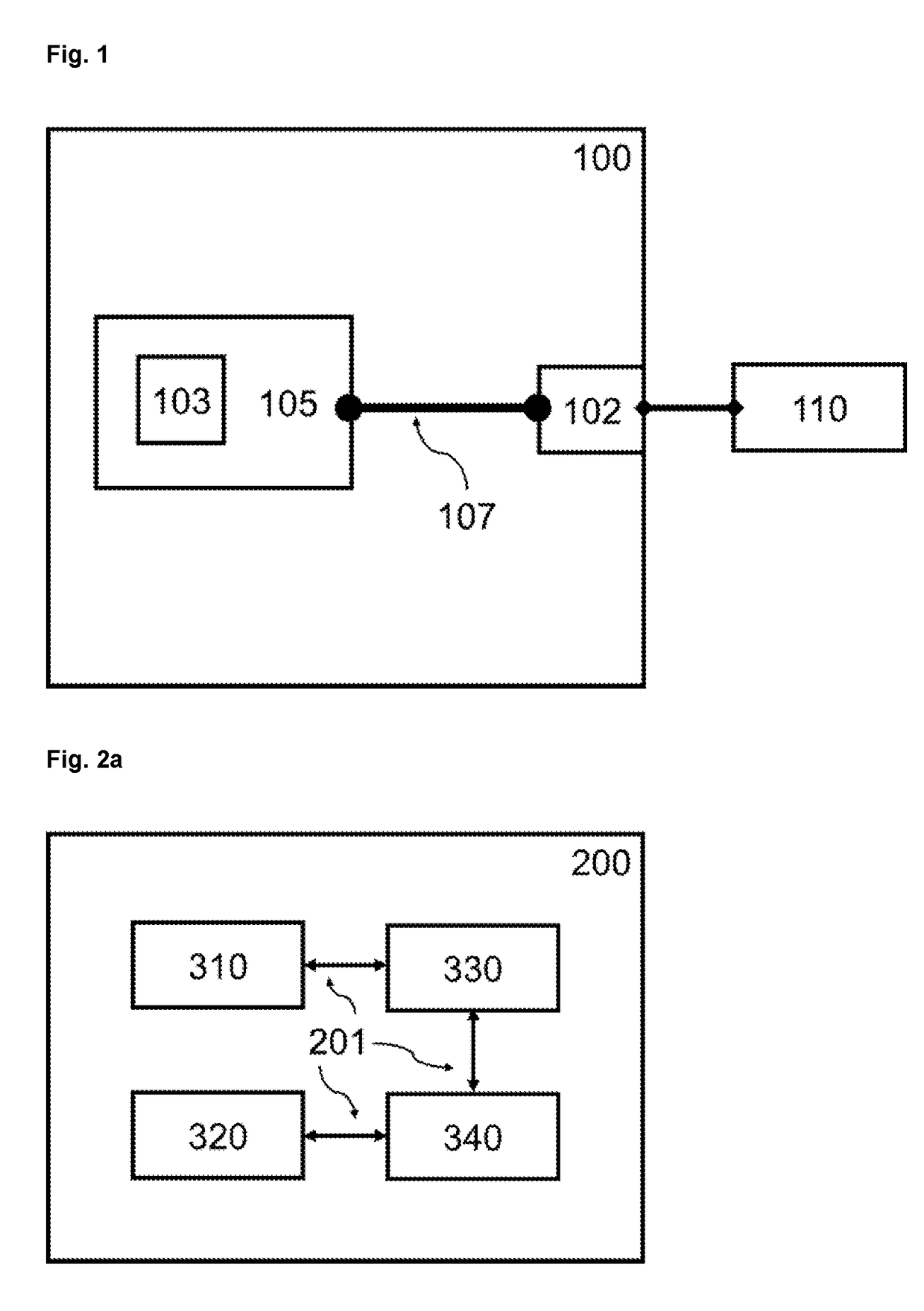
[0048]FIG. 1 shows a test device 100 on which a software model 103 of a technical system is executed on a calculation unit 105, wherein the software model or the calculation unit communicates via an input / output interface 102 of the test device, and an internal data connection 107 communicates with a device 110 connected to the test device. A calculation unit may be, e.g., a processor, an FPGA or an embedded PC. The communication with the test device can take place via the transmission of analog or digital electrical signals. The test device may include various hardware units (e.g., riser cards) that form the input / output interface 102. The input-output interface and the calculation unit 105 form a coherent system, but can also be spatially separated from each other and connected to each other via electronic connections.

[0049]For example, the test device 100 may be a hardware-in-the-loop (HIL) simulator. The test device 100 may also be a “Rapid Control Prototyping” (RCP) system. The...


PUM


Abstract

A configuration system for a test device designed for testing an electronic control unit. The test device is a hardware-in-the-loop simulator or a rapid control prototyping simulator, wherein a software model of a technical system is executed on the test device and the software model communicates electronically via an input/output interface of the test device with a system to be tested that is connected to the test device. Simulation data is electronically transmitted by the communication, and the configuration system is coupled to a modeling system and in the modeling system is a software model characterized by transversely and longitudinally connected function blocks. The configuration system configures the test device by interconnected configuration items such that the configuration items determine the physical characteristics of the input/output interface and/or the connection of the input/output interface with the software model.

Description

[0001]This nonprovisional application claims priority under 35 U.S.C. § 119(a) to German Patent Application No. DE 10 2017 120 016.9, which was filed in Germany on Aug. 31, 2017, and which is herein incorporated by reference.BACKGROUND OF THE INVENTIONField of the Invention[0002]The present invention relates to the development of control units, as are used e.g., in the automotive industry or in the aerospace industry for the control of technical systems, such as motors or brakes. In particular, the present invention relates to test devices used in the development process of the control unit.Description of the Background Art[0003]The development of control units has become a highly complex process. Thus, new control units or new control functions should be tested as early as possible in the development process to check general functionality and to specify the further direction of development. Towards the end of the development process, it is important to test the already well-develop...

Claims


Application Information

Patent Timeline
IPC IPC(8): G06F11/36
CPCG06F11/3688G06F11/3684G06F11/3692G06F11/3664G06F11/22
Inventor HAGENDORF, JOERGKRONMUELLER, MARTIN
Owner DSPACE DIGITAL SIGNAL PROCESSING & CONTROL ENG
Why Eureka
Try Eureka