Instrument force sensor using strain gauges in a faraday cage

a strain gauge and faraday cage technology, applied in the field of strain gauges, can solve the problems of limiting the useful life of surgical instruments, affecting the operation efficiency of surgical instruments, and the deformation of the epoxy glue used to attach the fibers to the shaft 102

Active Publication Date: 2019-03-07
INTUITIVE SURGICAL OPERATIONS INC
View PDF3 Cites 107 Cited by
  • Summary
  • Abstract
  • Description
  • Claims
  • Application Information

AI Technical Summary

Problems solved by technology

Unfortunately, the epoxy glue used to attach the fibers to shaft 102 degrades when cleaned in an autoclave machine.
This may result in a need to recalibrate the sensors, and also may limit the useful life of the surgical instrument with respect to force sensing if the epoxy glue fails.

Method used


Image

  • Instrument force sensor using strain gauges in a faraday cage
  • Instrument force sensor using strain gauges in a faraday cage
  • Instrument force sensor using strain gauges in a faraday cage

Examples


Embodiment Construction

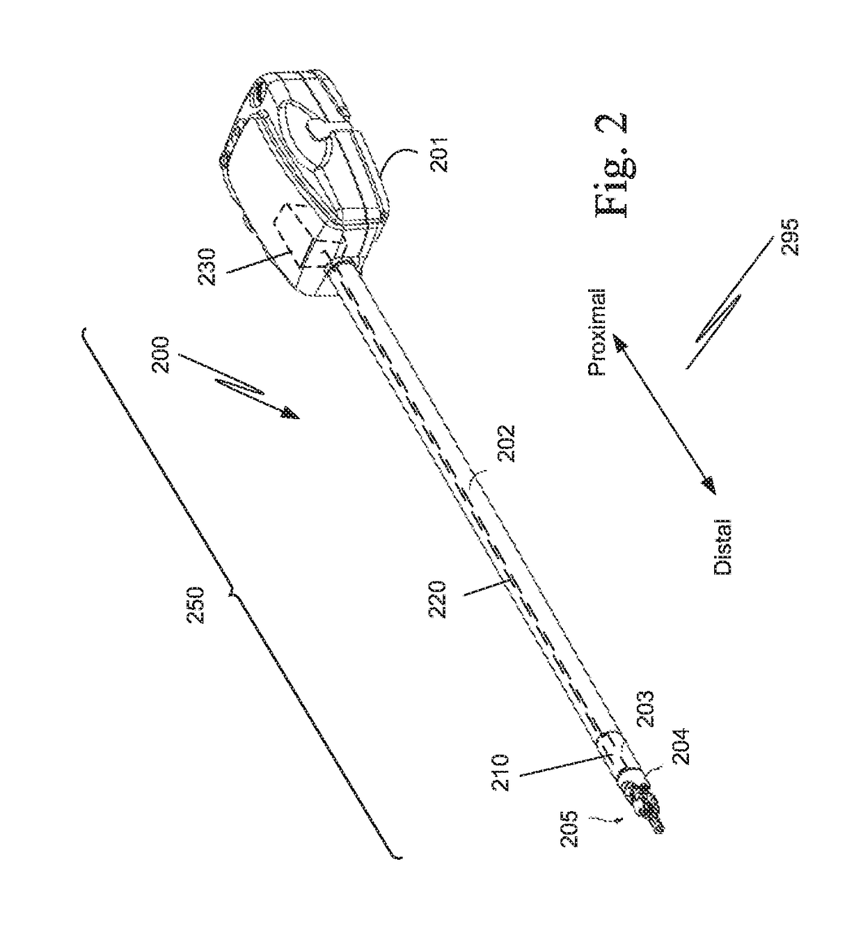
[0033]A surgical instrument 200 includes a force sensor apparatus 203 that is immune to noise from arcing cautery without relying on fiber optic strain gauges and that is autoclabable. Surgical instrument 200 includes a housing 201, a shaft 202, a force sensor apparatus 203, a joint 204, and an end component 205. End component 205, such as a surgical end effector, is coupled to force sensor apparatus 203 via joint 204, e.g., a wrist joint. Force sensor apparatus 203 is coupled to a distal end of a shaft 202 and is coupled to joint 204. Housing 201 is coupled to a proximal end of shaft 202, and housing 201 includes an interface which mechanically and electrically couples instrument 200 to an instrument manipulator assembly. In FIG. 2, arrow 295 defines the proximal and distal directions.

[0034]As explained more completely below, force sensor apparatus 203 includes at least one strain gauge that is enclosed in a Faraday cage 250. Faraday cage 250 includes a sensor capsule 210 that incl...


PUM


Abstract

A surgical instrument includes a force sensor apparatus that is immune to noise from arcing cautery without relying on fiber optic strain gauges, and that is autoclabable. The surgical instrument includes a housing, a shaft, the force sensor apparatus, a joint, and an end component. The force sensor apparatus includes at least one strain gauge that is enclosed in a Faraday cage. The Faraday cage includes a sensor capsule that includes one or more strain gauges, a cable shield tube connected to the sensor capsule, and an electronics enclosure connected to the cable shield tube. The sensor capsule is positioned between the joint and the shaft. The cable shield tube extends through the shaft to the electronics enclosure that is within the housing.

Description

RELATED APPLICATIONS[0001]This patent application claims priority to and the benefit of the filing date of U.S. Provisional Patent Application 62 / 290,010, entitled “INSTRUMENT FORCE SENSOR USING STRAIN GAUGES IN A FARADAY CAGE” filed Feb. 2, 2016, which is incorporated by reference herein in its entirety.BACKGROUNDField of the Invention[0002]The present invention relates generally to surgical instruments for computer-assisted surgical system, and more particularly to strain gauges used in surgical instruments for computer-assisted surgical systems.Description of Related Art[0003]FIG. 1 is a perspective illustration of a surgical instrument 100 used in a computer-assisted surgical system. Arrow 195 shows the proximal direction and the distal direction in FIG. 1.[0004]Surgical instrument 100 includes a housing 101, a shaft 102, a force sensor apparatus 103, a joint 104, and an end component 105. End component 105, such as a surgical end effector, is coupled to force sensor apparatus 3...

Claims


Application Information

Patent Timeline
Patent Type & Authority Applications(United States)
IPC IPC(8): A61B34/00A61B90/00
CPCA61B34/71A61B90/06A61B2090/065A61B2090/064A61B2562/0261A61B2562/12A61B2562/182A61B2018/00595
Inventor PETERSEN, ALAN W.LABONVILLE, GERARD J.STEGER, JOHN RYAN
Owner INTUITIVE SURGICAL OPERATIONS INC
Why Eureka
Try Eureka