Offshore structure mating system and installation method

a technology for offshore structures and installation methods, which is applied in the direction of machines/engines, final product manufacturing, and passenger handling devices, etc., can solve the problems of large installation costs, affecting the economic feasibility of certain environments, and the use of large offshore cranes, so as to reduce relative motion and load, reduce installation costs, and isolate the roll and pitch motion of the vessel.

Active Publication Date: 2019-03-07
SOFEC
View PDF11 Cites 18 Cited by
  • Summary
  • Abstract
  • Description
  • Claims
  • Application Information

AI Technical Summary

Benefits of technology

[0007]The present invention is a system and method of installing equipment offshore on a floating hull, such as a spar buoy, without using a large offshore crane. The system and method is suitable for installing a wind turbine generator on a spar buoy in a cost effective, safe and timely manner. The invention makes use of a gimbal table that grips the spar buoy from the bow or stern of a fork-type vessel and thereby isolates the roll and pitch motions of the vessel from the spar buoy. This greatly reduces the relative motions and loads during mating and thereby reduces risks. It may also be configured to handle larger installation environm

Problems solved by technology

In the field of floating offshore alternative energy projects, installation costs are significant enough to drive the project away from being economically feasible in certain environments.
Typical installation of a topside component, such as a wind turbine, on a floating hull, such as a spar buoy, requires the use of a very expensive large offshore crane.
The limited numbers of such cranes along with their operational and mobilization costs combine to drive up their expense and drive down their availability on demand.
The use of a standard b

Method used


Image

  • Offshore structure mating system and installation method
  • Offshore structure mating system and installation method
  • Offshore structure mating system and installation method

Examples


Embodiment Construction

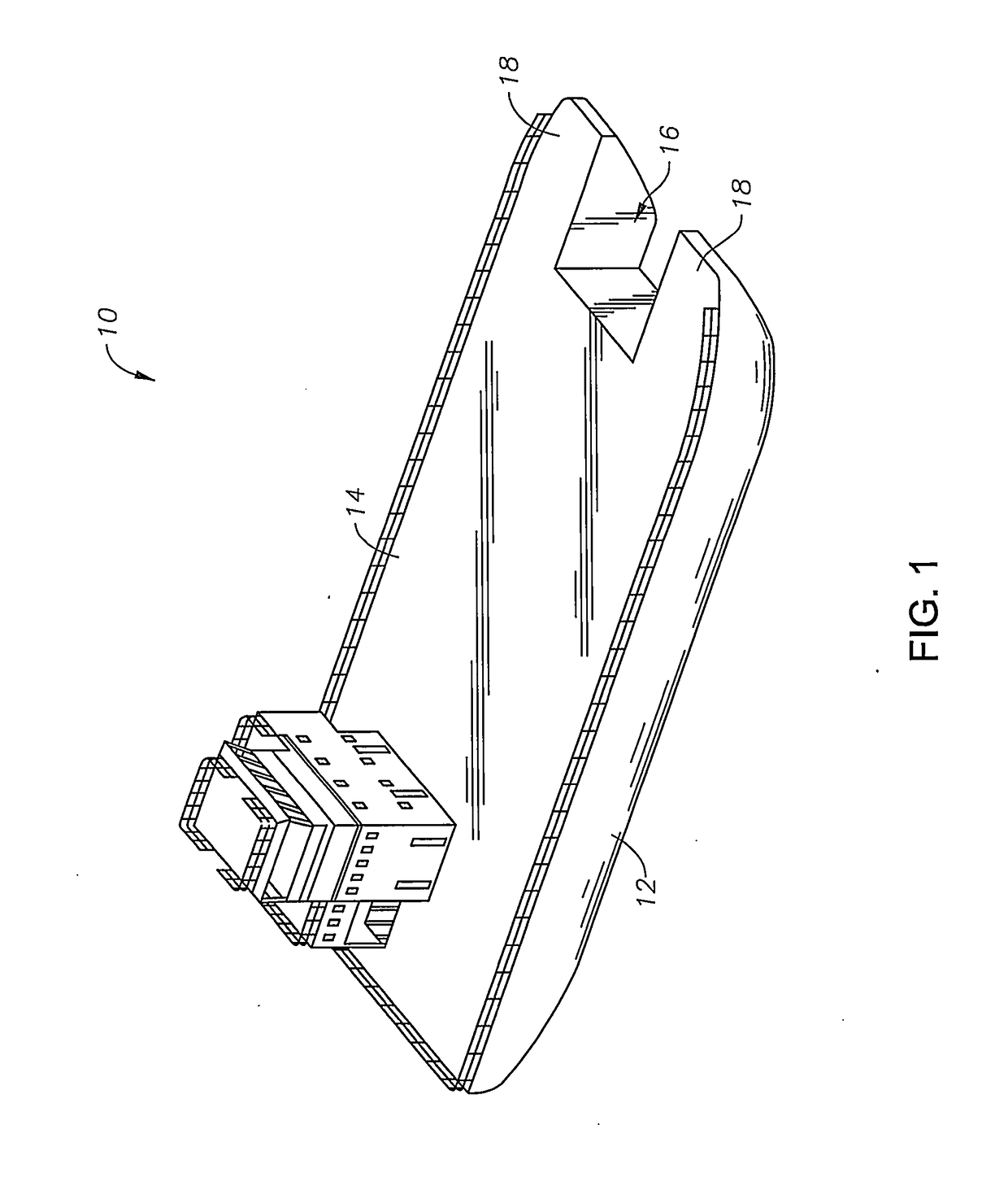
[0017]The preferred embodiments of the present invention will now be described in detail with reference to the figures. FIG. 1 shows an exemplary embodiment of a transport vessel 10 according to the invention. The transport vessel 10 includes a hull 12 having a deck 14. A pair of forks 18 defining a slot 16 are formed in the hull 12 or extend from the hull 12. The forks 18 and slot 16 are preferably at the bow or stern of the fork-type vessel 10.

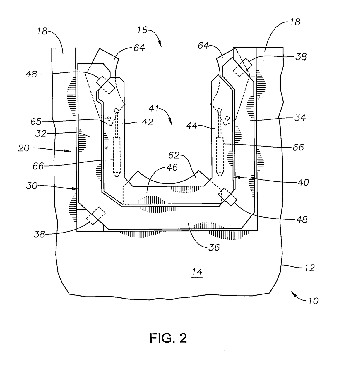
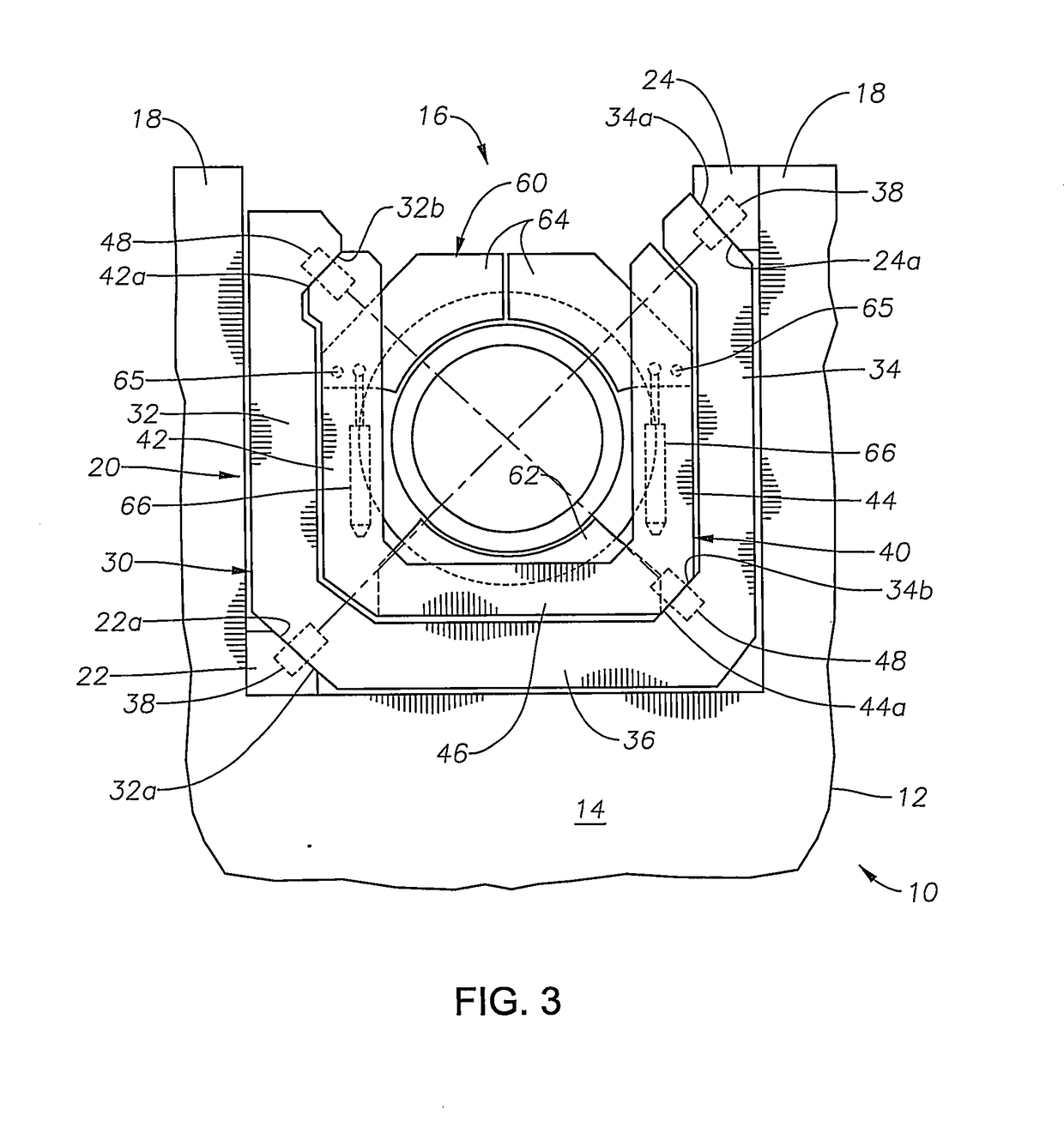
[0018]In a preferred embodiment of the present invention, a gimbal table 20 is positioned within the slot 16 between the forks 18 as shown in FIGS. 2, 3 and 4. The gimbal table 20 includes two nested tables 30, 40 that are open-ended and located between (or on top of) the vessel forks 18. An outer table 30 is generally U-shaped in plan view as shown in FIGS. 2 and 3. The outer table 30 has outer first and second legs 32 and 34, substantially parallel to one another, extending generally transversely from an outer base segment 36. As shown in ...


PUM


Abstract

A system and method for mating equipment offshore to a spar buoy secured to a foundation without the use of a crane barge. The system comprises a floating vessel having a pair of forks defining a slot. A gimbal table, defining an opening, is positioned within the slot and connected to the vessel and a locking collar is mounted to the gimbal table. A mating member is attached to the spar buoy. The vessel is maneuvered to bring the spar buoy within the gimbal table opening. With the spar buoy positioned within the gimbal table opening, the locking collar is arranged and designed to releasably attach to the mating member of the spar buoy and restrict relative vertical motion between the spar buoy and the vessel while the gimbal table allows the floating vessel to roll and pitch without driving these motions into the spar buoy.

Description

CROSS REFERENCE TO RELATED APPLICATIONS[0001]Not applicable.BACKGROUND OF THE INVENTION1. Field of the Invention[0002]The present invention generally relates to a method and system for installing equipment offshore on a floating hull, and more particularly relates to a method and system for installing a wind turbine generator on a floating hull offshore without using a large offshore crane.2. Description of the Related Art[0003]In the field of floating offshore alternative energy projects, installation costs are significant enough to drive the project away from being economically feasible in certain environments. Typical installation of a topside component, such as a wind turbine, on a floating hull, such as a spar buoy, requires the use of a very expensive large offshore crane. The limited numbers of such cranes along with their operational and mobilization costs combine to drive up their expense and drive down their availability on demand.[0004]The use of a standard barge / fork-typ...

Claims


Application Information

Patent Timeline
IPC IPC(8): E02B17/02B63B35/44F03D13/25
CPCE02B17/024B63B35/44B63B2035/446E02B2017/0047B63B2021/505F03D13/25F05B2230/6102F03D13/10B63B2035/442E02B2017/0043E02B2017/0065E02B2017/0091B63B75/00B63B27/30Y02P70/50Y02E10/727E02B17/027
Inventor LINDBLADE, STEPHEN P.NATARAJAN, ANANTH
Owner SOFEC
Why Eureka
Try Eureka