Method and control system for faulted phase detection

a technology of protection relay and faulted phase, which is applied in the direction of fault location by conductor type, short-circuit testing, instruments, etc., can solve the problems of increasing the cost and technical challenge of product implementation, and the failure of faulted phase detection based on fault component phase voltage to operate, etc., and achieve good sensitivity

Active Publication Date: 2019-03-07
HITACHI ENERGY SWITZERLAND AG
View PDF0 Cites 10 Cited by
  • Summary
  • Abstract
  • Description
  • Claims
  • Application Information

AI Technical Summary

Benefits of technology

[0004]Present invention provides another kind of faulted phase detection method and system based on a lumped parameter, sampling values and differential equation for the transmission lines. This method has good sensitivity for differential SIR conditions thanks to the voltage compensation. And furthermore, it is also a low-cost solution because it can be based on the low sampling rate like 1 k Hz.

Problems solved by technology

For example, the faulted phase detection based on fault component phase voltages will fail to operate if the SIR is close to zero, when the power system is too strong and the fault component voltages at the ends of the transmission lines are too small.
This method is widely used but it is not suitable for the time-domain protections.
This method is designed for time domain protections and travelling wave protections, but it needs much higher sampling rate to achieve enough calculation accuracy, which increases the cost and technical challenge for product implementation.

Method used


Image

  • Method and control system for faulted phase detection
  • Method and control system for faulted phase detection
  • Method and control system for faulted phase detection

Examples


Embodiment Construction

[0031]In the following description, for purposes of explanation and not limitation, specific details are set forth, such as particular circuits, circuit components, interfaces, techniques, etc. in order to provide a thorough understanding of the present invention. However, it will be apparent to one skilled in the art that the present invention may be practiced in other embodiments that depart from these specific details. In other instances, detailed descriptions of well-known methods and programming procedures, devices, and circuits are omitted so not to obscure the description of the present invention with unnecessary detail.

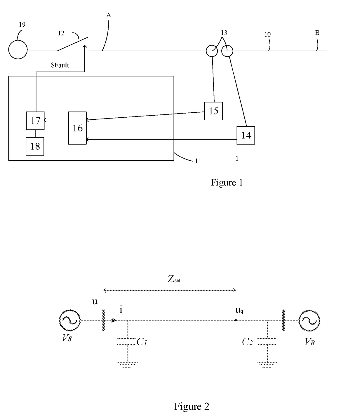
[0032]FIG. 1 shows an AC power system according to an embodiment of present invention. As shown in FIG. 1, the AC power system 1 includes a transmission line 10 defined at its two ends A and B. A protective relay 11, in the event of a fault, may disconnect the affected phase of the transmission line 10, for example by its power circuit breaker 12. An AC source...


PUM


Abstract

A method, control system and protective relay are provided for detecting faulted phases of transmission lines in an AC power system. The method includes sampling electric signals at one end of the transmission lines at a series of time points; computing instantaneous voltage values of electric signals at compensated points on the transmission lines from the values of the sampled electric signals based on a time domain lumped parameter differential equation for the transmission lines for the series of time points; recording the computed instantaneous voltage values of the electric signals; computing fault component or sudden-change of the instantaneous voltage values of the electrical signals; detecting the faulted phases or fault types by comparing the calculated fault component of the instantaneous voltage values at the preset compensated points; and generating signals indicating the faulted phases of fault types.

Description

TECHNICAL FIELD[0001]The invention relates to protection relay of AC power system, and more particularly to faulted phase detection for protection relay of AC power system.BACKGROUND ART[0002]Faulted phase detection which is also called faulted phase selection, fault classification or fault type detection is an important function for protection relay, especially for single-pole tripping power system. Normally, the faulted phase detection is based on the comparison of the fault component currents or voltages from different phases, or based on the comparison of currents or voltages from different sequences.[0003]But the sensitivities of these methods are influenced greatly by the SIR of the power system. For example, the faulted phase detection based on fault component phase voltages will fail to operate if the SIR is close to zero, when the power system is too strong and the fault component voltages at the ends of the transmission lines are too small. Voltage compensation is used to ...

Claims


Application Information

Patent Timeline
Patent Type & Authority Applications(United States)
IPC IPC(8): G01R31/02H02H3/16
CPCG01R31/025H02H3/165G01R19/2513G01R31/085G01R31/52H02H3/385H02H7/26G01R31/50
Inventor LIU, KAIWANG, JIANPINGLI, YOUYI
Owner HITACHI ENERGY SWITZERLAND AG
Why Eureka
Try Eureka