Apparatus and Methods of Evaluating Rock Properties While Drilling Using Acoustic Sensors Installed in the Drilling Fluid Circulation System of a Drilling Rig

a technology of acoustic sensors and drilling rigs, which is applied in the field of hydrocarbon production, can solve the problems of not being able to construct additional interpretation models, nearly impossible to modify any interpretation models generated by the drilling process, and not being able to use tools that are real-time tools. , to achieve the effect of better drilling steering

Active Publication Date: 2019-03-07
SAUDI ARABIAN OIL CO
View PDF0 Cites 3 Cited by
  • Summary
  • Abstract
  • Description
  • Claims
  • Application Information

AI Technical Summary

Benefits of technology

The present invention relates to an apparatus and method for better drilling steering by providing detailed information about the rock that is currently in contact with the drilling bit. By analyzing the acoustic characteristics of the rock and comparing them to the acoustic characteristics of rock samples, the driller can make real-time decisions to steer the drilling bit to follow the desire path more accurately. This approach allows for smoother drilling of lateral or horizontal wells with better contact with the production zone, as well as detecting formation boundaries and fractured zones in real-time. The invention provides an effective way to drill safer and more efficient wells.

Problems solved by technology

Therefore, these tools are not true real-time tools.
Although providing data in a reduced form requiring only a bit rate speed, as such systems do not provide raw data real-time which can be used for further analysis, it is nearly impossible to construct additional interpretation models or modify any interpretation models generated by the downhole processor.

Method used


Image

  • Apparatus and Methods of Evaluating Rock Properties While Drilling Using Acoustic Sensors Installed in the Drilling Fluid Circulation System of a Drilling Rig
  • Apparatus and Methods of Evaluating Rock Properties While Drilling Using Acoustic Sensors Installed in the Drilling Fluid Circulation System of a Drilling Rig
  • Apparatus and Methods of Evaluating Rock Properties While Drilling Using Acoustic Sensors Installed in the Drilling Fluid Circulation System of a Drilling Rig

Examples


Embodiment Construction

[0047]The present invention will now be described more fully hereinafter with reference to the accompanying drawings, which illustrate embodiments of the invention. This invention may, however, be embodied in many different forms and should not be construed as limited to the illustrated embodiments set forth herein. Rather, these embodiments are provided so that this disclosure will be thorough and complete, and will fully convey the scope of the invention to those skilled in the art. Like numbers refer to like elements throughout. Prime notation, if used, indicates similar elements in alternative embodiments.

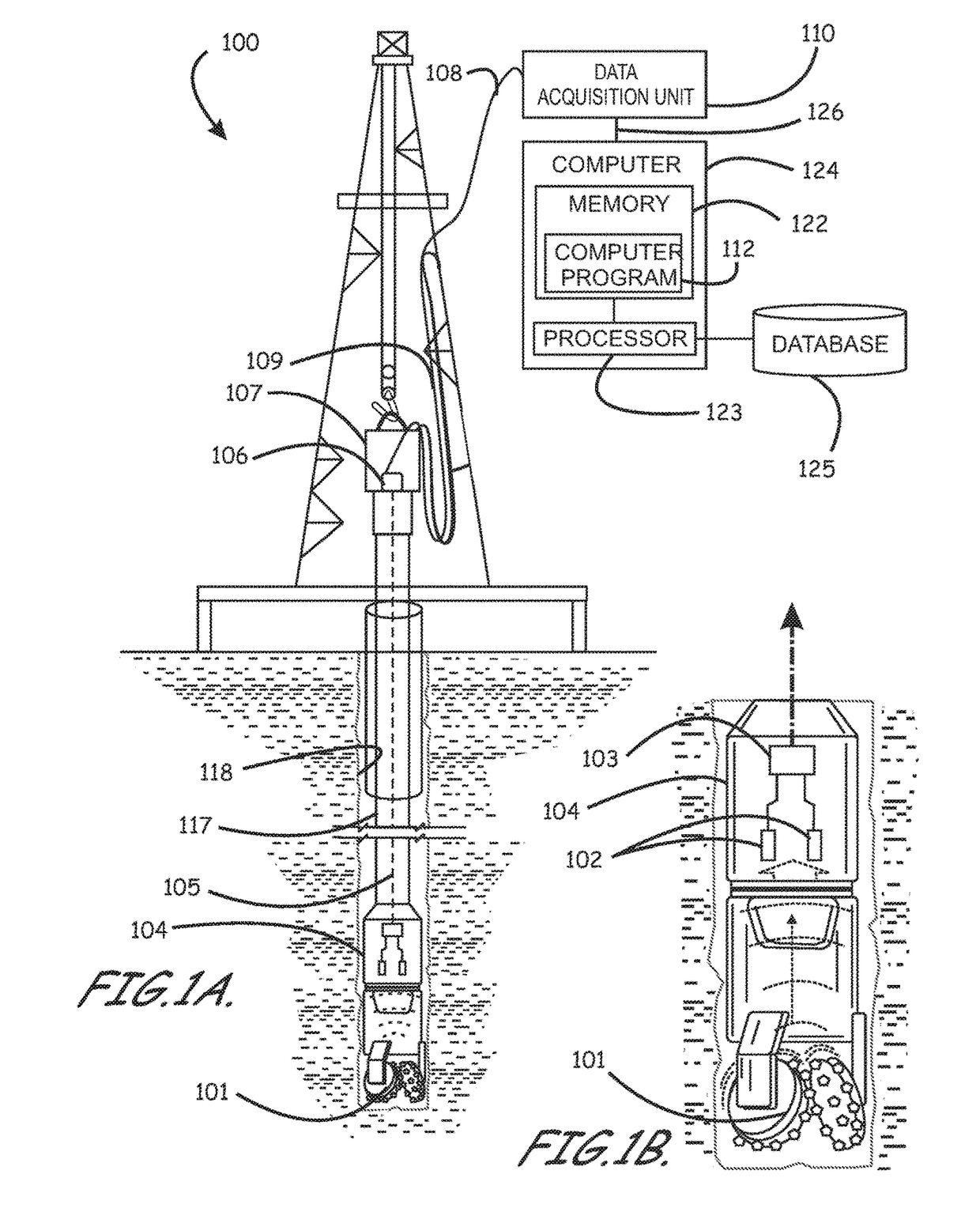
[0048]When drilling into different lithologies or the same lithology with different properties (e.g., porosity, water saturation, permeability, etc.) the generated acoustic sounds emanating from the drill bit when drilling into rock, are distinctly different. The sounds, termed as drilling acoustic signals hereafter, transmit upward along the drill string. According to various ...


PUM


Abstract

Apparatus and methods of identifying rock properties in real-time during drilling, are provided. An apparatus includes an acoustic sensor installed in a drilling fluid circulation system of a drilling rig, the acoustic sensor coupled to one of the following: (i) a bell nipple, (ii) a gooseneck, or (iii) a standpipe. Raw acoustic sensor data generated real-time as a result of rotational contact of the drill bit with rock during drilling is received, and a plurality of acoustic characteristics are derived from the raw acoustic sensor data. The lithology type of rock undergoing drilling may be determined from the acoustic characteristics. Petrophysical properties of the rock undergoing drilling may be determined using a petrophysical properties evaluation algorithm employable to predict the petrophysical properties of rock undergoing drilling from the raw acoustic sensor data.

Description

RELATED APPLICATIONS[0001]This application is a continuation-in-part of and claims priority to and the benefit of U.S. Non-Provisional patent application Ser. No. 13 / 554,369 titled “Methods Of Evaluating Rock Properties While Drilling Using Downhole Acoustic Sensors And A Downhole Broadband Transmitting System” filed on Jul. 20, 2012, which is a non-provisional of and claims priority to and the benefit of U.S. Provisional Patent Application No. 61 / 539,171, titled “Methods Of Evaluating Rock Properties While Drilling Using Downhole Acoustic Sensors And A Downhole Broadband Transmitting System,” filed on Sep. 26, 2011, and is related to U.S. patent application Ser. No. 13 / 554,019, filed on Jul. 20, 2012, titled “Apparatus, Computer Readable Medium and Program Code for Evaluating Rock Properties While Drilling Using Downhole Acoustic Sensors and Telemetry System”; U.S. patent application Ser. No. 13 / 553,958, filed on Jul. 20, 2012, titled “Methods of Evaluating Rock Properties While Dr...

Claims


Application Information

Patent Timeline
IPC IPC(8): G01V1/16G01V1/50
CPCG01V1/168G01V1/50G01V1/162G01V2200/16G01V2210/1425G01V2210/1216
Inventor YANG, YUNLAI
Owner SAUDI ARABIAN OIL CO
Why Eureka
Try Eureka