
Brain computer interface (BCI) apparatus and method of generating control signal by bci apparatus

a technology of brain computer interface and control signal, which is applied in the field of brain computer interface (bci) apparatus and the method of generating control signal by the bci apparatus, can solve the problems of limited application of bci technology to daily life and method of detecting and processing various motor imageries, and achieve the effect of suppressing the robot arm device and accurately generating control signal

Active Publication Date: 2019-03-07
KOREA UNIV RES & BUSINESS FOUND
View PDF0 Cites 27 Cited by
  • Summary
  • Abstract
  • Description
  • Claims
  • Application Information

AI Technical Summary

Benefits of technology

This patent describes a method and device that can accurately control a robot arm using a person's motor imaging and a brain-computer interface (BCI). The method involves quickly determining a control mode based on an abstract feature and giving feedback to the person to check if it matches their motor imaging. This allows for more precise control of the robot arm. The process of determining the control mode is separate from the process of actually controlling the robot arm, and each control mode can be controlled more precisely. This technology can be used in a range of applications, such as in robotics or rehabilitation.

Problems solved by technology

However, conventional apparatuses using the BCI technology have been used only to detect and process a specific motor imagery.
Therefore, the BCI technology has been limited in application to daily life.
However, this method is still limited to detecting and processing various motor imageries.

Method used


Image

  • Brain computer interface (BCI) apparatus and method of generating control signal by bci apparatus
  • Brain computer interface (BCI) apparatus and method of generating control signal by bci apparatus
  • Brain computer interface (BCI) apparatus and method of generating control signal by bci apparatus

Examples


Embodiment Construction

[0018]Hereinafter, embodiments of the present disclosure will be described in detail with reference to the accompanying drawings so that those skilled in the art may readily implement the present disclosure. However, it is to be noted that the present disclosure is not limited to the embodiments but can be embodied in various other ways. In drawings, parts irrelevant to the description are omitted for the simplicity of explanation, and like reference numerals denote like parts through the whole document.

[0019]Through the whole document, the term “connected to” or “coupled to” that is used to designate a connection or coupling of one element to another element includes both a case that an element is “directly connected or coupled to” another element and a case that an element is “electronically connected or coupled to” another element via still another element. Further, it is to be understood that the term “comprises or includes” and / or “comprising or including” used in the document ...


PUM


Abstract

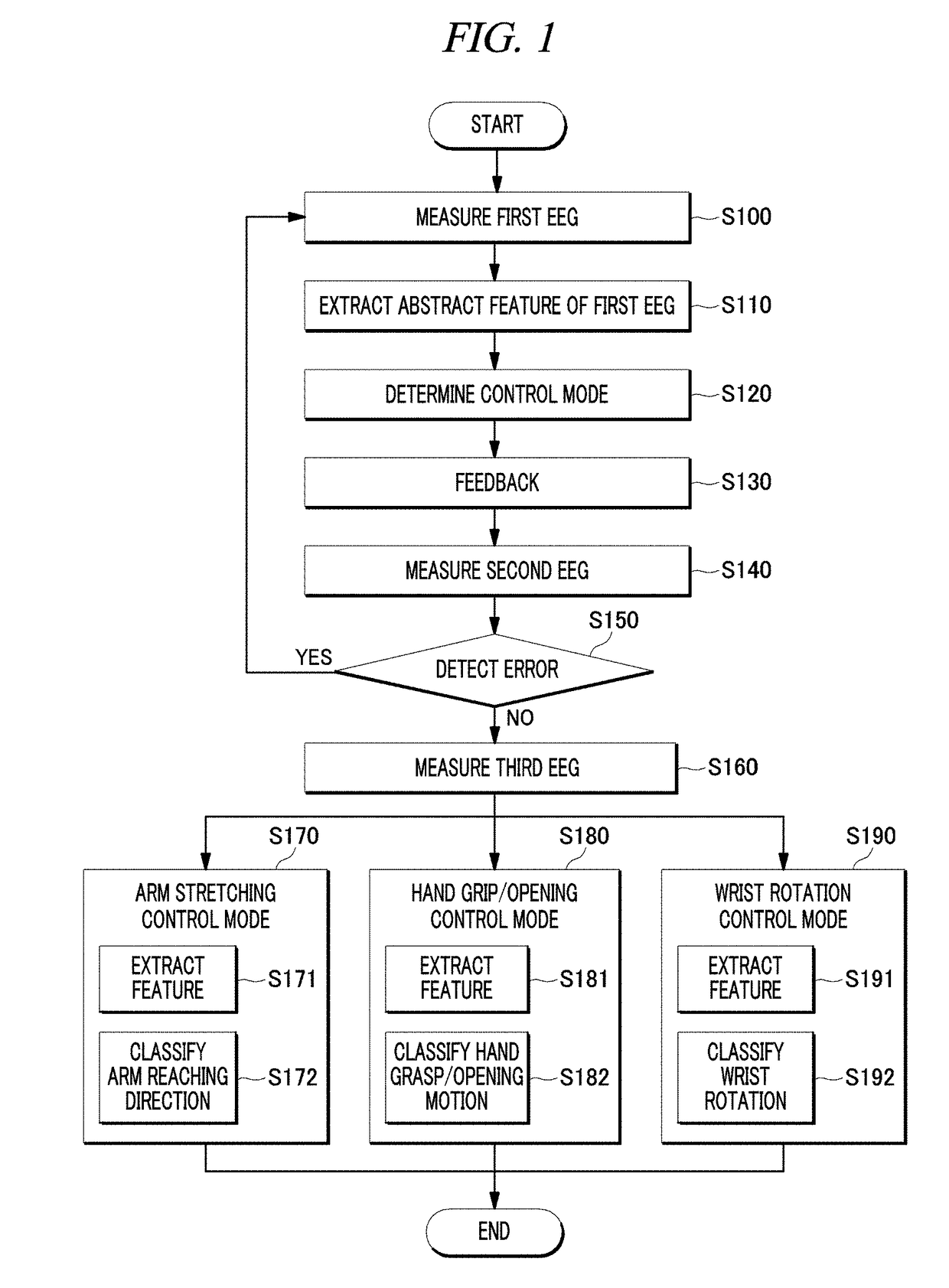
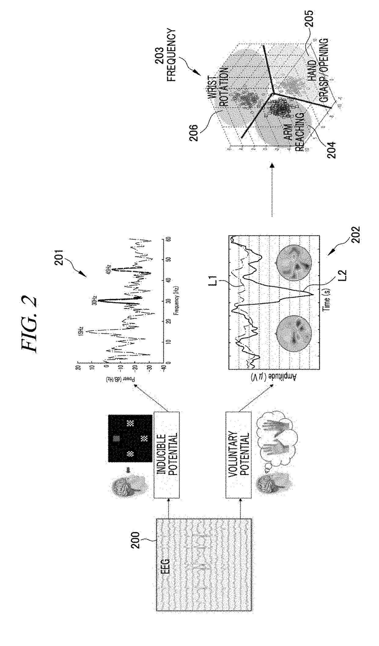
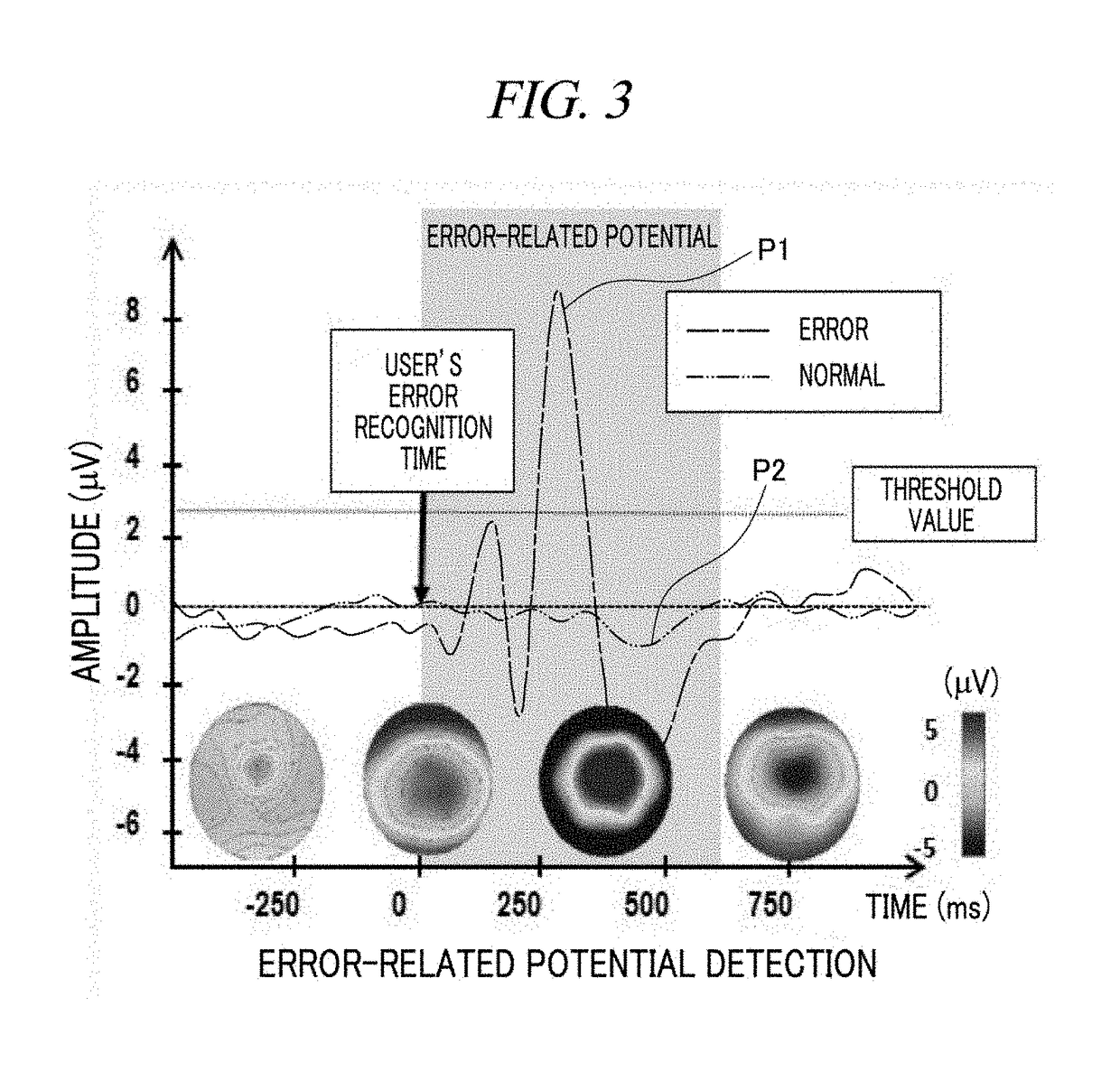
The present disclosure provides a method of generating a control signal to control a motion of a robot arm device by a brain-computer interface (BCI) apparatus and the BCI apparatus. The present method includes: measuring a first electroencephalogram (EEG) and extracting an abstract feature of the first EEG; determining one of an reaching control mode, a hand grasp / opening control mode, and a wrist rotation control mode based on the abstract feature of the first EEG; performing feedback of the determined control mode to a user; measuring an error-related potential as a second EEG; redetermining the control mode by re-extracting an abstract feature of the first EEG when the error-related potential exceeds a threshold value or measuring a third EEG when the error-related potential does not exceed the threshold value; extracting a result value by applying different feature extraction methods and different classification methods to the third EEG depending on the determined control mode; and supplying a control signal generated based on the result value to the robot arm device.

Description

CROSS-REFERENCE TO RELATED APPLICATION[0001]This application claims the benefit under 35 USC 119(a) of Korean Patent Application No. 10-2017-0114617 filed on Sep. 7, 2017 in the Korean Intellectual Property Office, the entire disclosures of which are incorporated herein by reference for all purposes.TECHNICAL FIELD[0002]The present disclosure relates to a brain-computer interface (BCI) apparatus capable of more accurately generating a control signal to control a motion of a subject and a method of generating a control signal by the BO apparatus.BACKGROUND[0003]In general, brain waves can be classified into various types depending on their temporal feature, frequency band feature, and spatial feature are classified as follows. That is, the brain waves are classified into an alpha wave (frequency of 8 Hz to 13 Hz, amplitude of 20 V to 60 V) generated during relaxation with eyes closed, a beta wave (frequency of 14 Hz to 30 Hz, amplitude of 2 V to 20 V) generated during conscious conce...

Claims


Application Information

Patent Timeline
Patent Type & Authority Applications(United States)
IPC IPC(8): G06F3/01B25J9/16A61B5/375
CPCG06F3/015B25J9/1689A61B5/0482A61B5/0476A61B5/7275B25J9/1612A61B5/7264B25J9/161B25J13/087G16H50/20A61B5/375A61B5/369A61F2/54A61F2/72A61F2002/704A61B5/374A61B5/7253A61B5/7225A61B5/7235
Inventor LEE, SEONG-WHANJEONG, JI-HOONKIM, KEUN-TAE
Owner KOREA UNIV RES & BUSINESS FOUND
Learn More