A floating wind turbine and a method for the installation of such floating wind turbine

a technology of floating wind turbines and wind turbines, which is applied in the direction of wind energy generation, vessel construction, anchoring arrangements, etc., can solve the problems of insufficient suitable offshore areas with water depths of 50 m or less, insufficient sheltered waters with sufficient depth, and inability to deploy offshore wind power, etc., to achieve effective installation arrangements of tlps, reduce tether forces, and reduce lateral movements

Active Publication Date: 2019-03-14
STIESDAL OFFSHORE AS
View PDF0 Cites 14 Cited by
  • Summary
  • Abstract
  • Description
  • Claims
  • Application Information

AI Technical Summary

Benefits of technology

[0076]This arrangement enables a particularly effective installation arrangement of a TLP, since the pre-installation of anchors and tethers is eliminated. The counterweight replaces pre-installed TLP anchors, and the counterweight suspension means replace pre-installed TLP tethers.
[0077]By suitable arrangement of the counterweight and its suspension the TLP will have very limited lateral movements, which not only serve to reduce the tether forces but also eliminate the need for elaborate flex joints at the tether attachments.

Problems solved by technology

In many areas of the world, sufficient suitable offshore areas with water depths of 50 m or less are not available for deployment of offshore wind power to the desired extent.
Some spar buoy designs seek to achieve additional benefits from taut mooring lines; these designs have not yet been tested in practice.
However, the draft poses major challenges during the installation and transportation phases.
Due to the motion of the sea it is generally not considered feasible to install wind turbines on floating foundations under ocean conditions at their final location, and therefore floating wind turbines are normally installed at quayside using land-based cranes, or in sheltered waters using floating cranes.
While it is fairly easy in a few countries, e.g. Norway to find sheltered waters with sufficient depth to permit wind turbine installation using a floating crane, in many parts of the world such sheltered waters with sufficient depth are not available.
Furthermore, even where such sheltered waters with sufficient depth are actually available in a region, the presence of ridges or shoals in the transportation corridor between the point of installation and the desired offshore locations will often effectively prevent the utilization of such sheltered waters for turbine installation.
These limitations caused by the deep draft of a spar pose a significant problem for the spar buoy concept.
This is generally not the case for large wind turbines, however.
Lubricants, coolants and other fluids pose a special problem; seals in bearings, gearboxes, hydraulics, expansion tanks, will need to be of special design to allow for near-horizontal orientation.
As a consequence of these factors, spar buoy installation methods based on near-horizontal orientation of the wind turbine are generally not attractive.
However, the stability concept, which is based on differential buoyancy arising as a consequence of heel, leads to considerable heeling angles during turbine operation due to the overturning moment created by the large lateral forces acting on the turbine rotor.
Firstly, through the introduction of active sensor and pumping systems a new level of complexity is introduced, inherently violating the fundamental principle that due to the challenges in accessibility unmanned offshore structures should have as few active systems as possible.
Secondly, since the masses that need to be redistributed are significant, measured in hundreds or thousands of tons, the balancing system will be semi-static, typically with time constants on the order of minutes even when very large pumps are used.
Consequently, transient changes in the overturning moment created by the large lateral forces acting on the turbine rotor cannot be balanced.
While the arrangement disclosed in U.S. Pat. No. 8,118,538 serves the purpose of reducing the heeling angle, the mounting method outlined is complicated.
The complexity of the operations and the cost of the winches make this arrangement unattractive.
This submersion process will typically cause the platform to become unstable, since the waterplane area will not be of sufficient dimension and distribution to ensure stability.
Completion of the installation on site requires considerable technical arrangements, such as sliding guides and winches.
This solution has the disadvantage that the towing resistance is significantly increased, reducing the weather window for installation.
Furthermore, the handling and release of the temporary buoyancy elements requires considerable offshore operations.
This solution has the benefit of easy towing and safe, simple offshore operations, but it has the very substantial drawback that the semisubmersible barge is a special vessel of considerable dimensions, which inherently leads to higher costs.
The problem remains, however, that the removal of the temporary tanks after the connection of the TLP to the tethers is a complicated offshore operation with significant risks of damage to the floater and / or the temporary tanks during the operation.
Furthermore, additional costs are associated with the purpose-built temporary tanks.
This arrangement has the advantage that towing and installation can be carried out in an efficient and safe manner, but as for Solutions A and C in the Iberdrola document, the solution has the very substantial drawback that the installation barge is a special vessel of considerable dimensions, which inherently leads to higher costs.
In this construction the installation of the TLP is difficult as the stability during lowering is unsecure.
None of the prior art documents disclose a combination of a counterweight and a TLP configuration.

Method used


Image

  • A floating wind turbine and a method for the installation of such floating wind turbine
  • A floating wind turbine and a method for the installation of such floating wind turbine
  • A floating wind turbine and a method for the installation of such floating wind turbine

Examples


Embodiment Construction

[0105]In the figures, similar or corresponding elements are denoted with the same reference numerals.

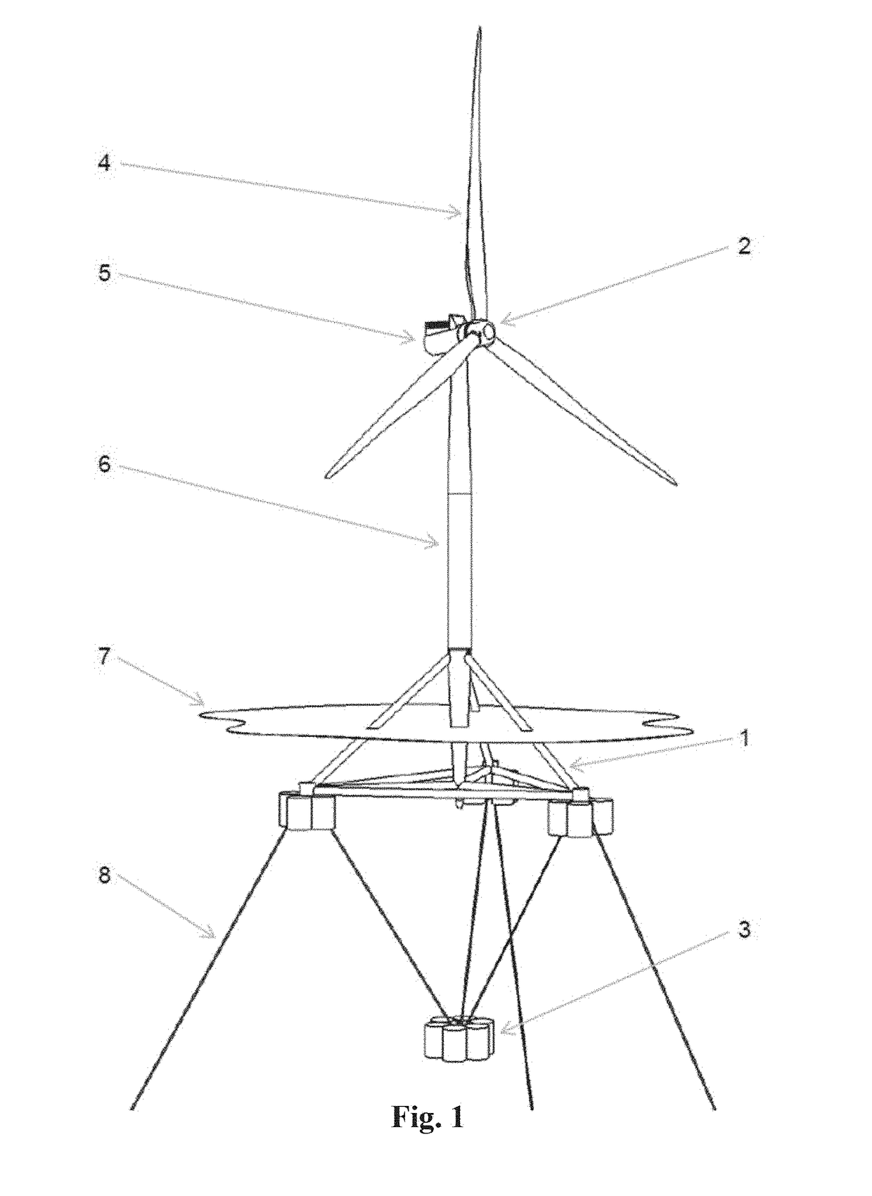
[0106]FIG. 1 shows a floating wind turbine according to embodiments of the invention. A floating foundation hull 1 supports a wind turbine 2 for electric power production. A counterweight 3 is suspended below the hull 1.

[0107]The wind turbine 2 comprises a rotor 4 for extracting kinetic energy from the wind, a nacelle 5 containing the equipment needed to support the rotor and to convert the rotational energy delivered by the rotor 4 into electric energy, and a tower 6 supporting the nacelle and the rotor.

[0108]The floating foundation hull 1 is partially submerged under the waterplane 7, and it is kept in position by mooring lines 8.

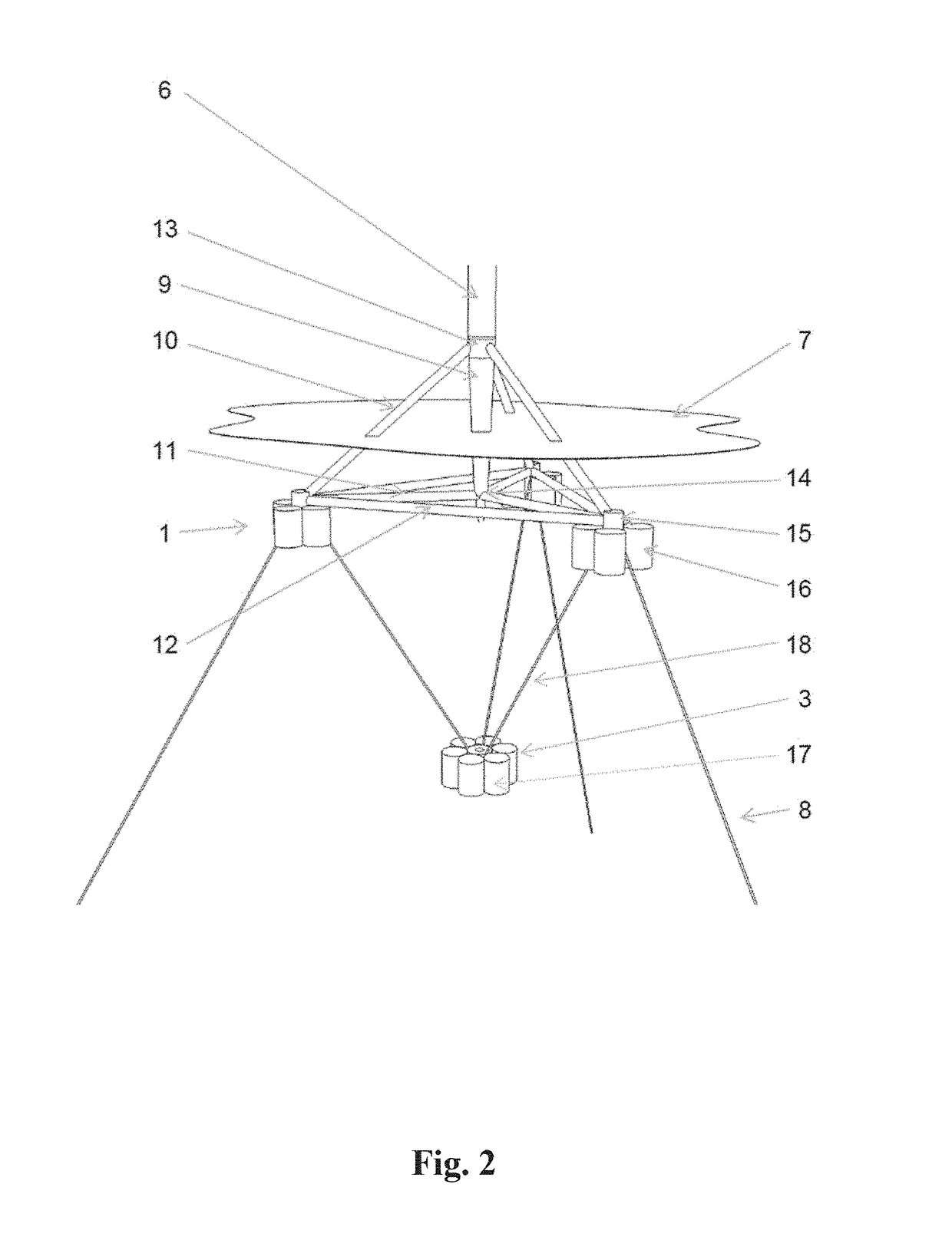
[0109]FIG. 2 shows the floating foundation hull 1 and the counterweight 3 in more detail. The floating foundation hull 1 may be implemented as a tetrahedral structure comprising a central column 9, three diagonal braces 10, three radial braces 11, and thre...


PUM


Abstract

Provided is a floating wind turbine including a hull, a wind turbine mounted on top of the hull and a counterweight suspended below the hull by a counterweight suspension is described. Also, a method for the installation is described. The counterweight includes one or more counterweight buoyancy tanks. When the internal volume of the buoyancy tanks is filled with air, the total buoyancy of the counterweight is close to or greater than its weight. Hereby it is capable of floating in a towing/maintenance position with moderate or no support in the vertical direction from the hull or other vessels. During towing, the hull substantially has the character of a barge, substantially relying on a large waterplane area and shallow draft to maintain stability.

Description

CROSS-REFERENCE TO RELATED APPLICATIONS[0001]This application claims priority to PCT Application No. PCT / DK2017 / 050076, having a filing date of Mar. 15, 2017, which is based on DK Application No. PA 2016 70761, having a filing date of Sep. 27, 2016 and DK Application No. PA 2016 70151, having a filing date of Mar. 15, 2016, the entire contents all of which are hereby incorporated by reference.FIELD OF TECHNOLOGY[0002]The following concerns a floating offshore foundation for a wind turbine, and installation and maintenance methods for the floating offshore foundation.[0003]More specific, embodiments of the invention concerns a floating wind turbine comprising a hull, a wind turbine mounted on top of the hull and a counterweight suspended below the hull by means of counterweight suspension means or a counterweight suspension.[0004]Moreover, embodiments of the invention concerns a method for the installation of a floating wind turbine comprising a hull, a wind turbine mounted on top of...

Claims


Application Information

Patent Timeline
Patent Type & Authority Applications(United States)
IPC IPC(8): F03D13/25B63B21/50B63B35/44
CPCF03D13/25B63B21/502B63B35/44B63B2035/446F05B2240/93B63B2207/02Y02E10/727Y02E10/72B63B77/10
Inventor STIESDAL, HENRIK
Owner STIESDAL OFFSHORE AS
Why Eureka
Try Eureka