Multi-band antenna array

Active Publication Date: 2019-03-14
MEDIATEK INC
View PDF0 Cites 20 Cited by
  • Summary
  • Abstract
  • Description
  • Claims
  • Application Information

AI Technical Summary

Benefits of technology

[0004]An objective of the invention is providing a multi-band antenna array (e.g., 100, 300a, 300b, 500a, 500b, 500c, 600a, 600b, 700, 800, 900a or 900b in FIG. 1, 3a, 3b, 5a, 5b, 5c, 6a, 6b, 7, 8, 9a or 9b) of improved compactness. The antenna array may include a plurality of first antennas (e.g., a1 to a4 in FIGS. 1, 2, 3a, 3b, 4a, 4b, 5a, 5b, 5c, 6a, 6b, 7 or 9b; a1 to a4 and a1c in FIGS. 9a; or, a1 to a9 in FIG. 8) for resonating at a first band (e.g., low-band), and a plurality of second antennas (e.g., b1 to b4 in FIG. 1, 2, 3a, 3b, 4a, 4b, 5a, 5b, 5c, 6a, 6b, 7 or 9a; or, b1 to b4 and b1c in FIG. 9b; or, b1 to b12 in FIG. 8) for resonating at a second band (e.g., low-band). A frequency of the second band may be higher than a frequency of the first band. Locations of the plurality of first antennas may respectively project to a plurality of grid-one positions (e.g., p1 to p4 in FIGS. 1, 2, 3a, 3b, 3c, 4a, 4b, 5a, 5b, 5c, 6a, 6b, 7 or 9b; or, p1 to p4 and p1c in FIGS. 9a; or, p1 to p9 in FIG. 8) on a surface (e.g., xy1 in FIG. 1, 2, 3a, 3b, 4a, 4b, 5a, 5b, 5c, 6a, 6b, 7, 8, 9a or 9b). Locations of the plurality of second antennas may respectively project to a plurality of grid-two positions (e.g., u1 to u4 in FIG. 1, 2, 3a, 3b

Problems solved by technology

In addition, limited form factor of wireles

Method used


Image

  • Multi-band antenna array
  • Multi-band antenna array
  • Multi-band antenna array

Examples


Embodiment Construction

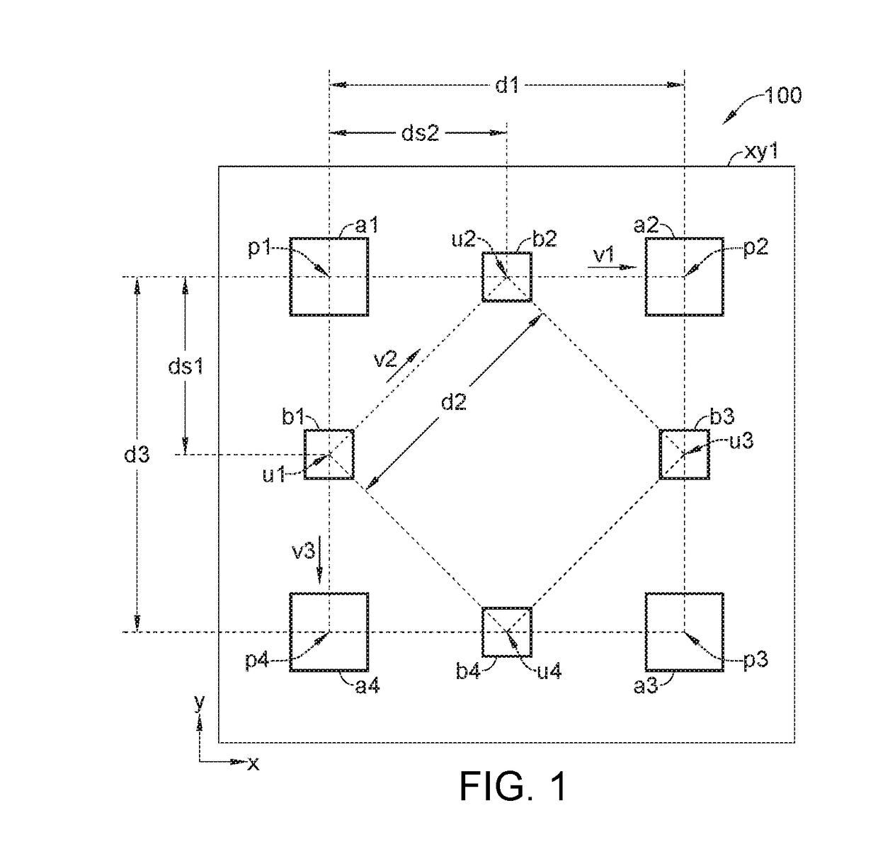
[0036]Please refer to FIG. 1 illustrating a top view of an antenna array 100 according to an embodiment of the invention; the antenna array 100 may be a multi-band antenna array (antenna module). The antenna array 100 may include a plurality of low-band antennas, such as a1, a2, a3 and a4, for electromagnetic resonating at a low-band of a frequency f1. The antenna array 100 may also include a plurality of high-band antennas, such as b1, b2, b3 and b4, for electromagnetic resonating at a high-band of a frequency f2. The frequency f2 of the high-band may be higher than the frequency f1 of the low-band. The low-band antennas a1 to a4 may form a low-band subarray, and the high-band antennas b1 to b4 may form a high-band subarray.

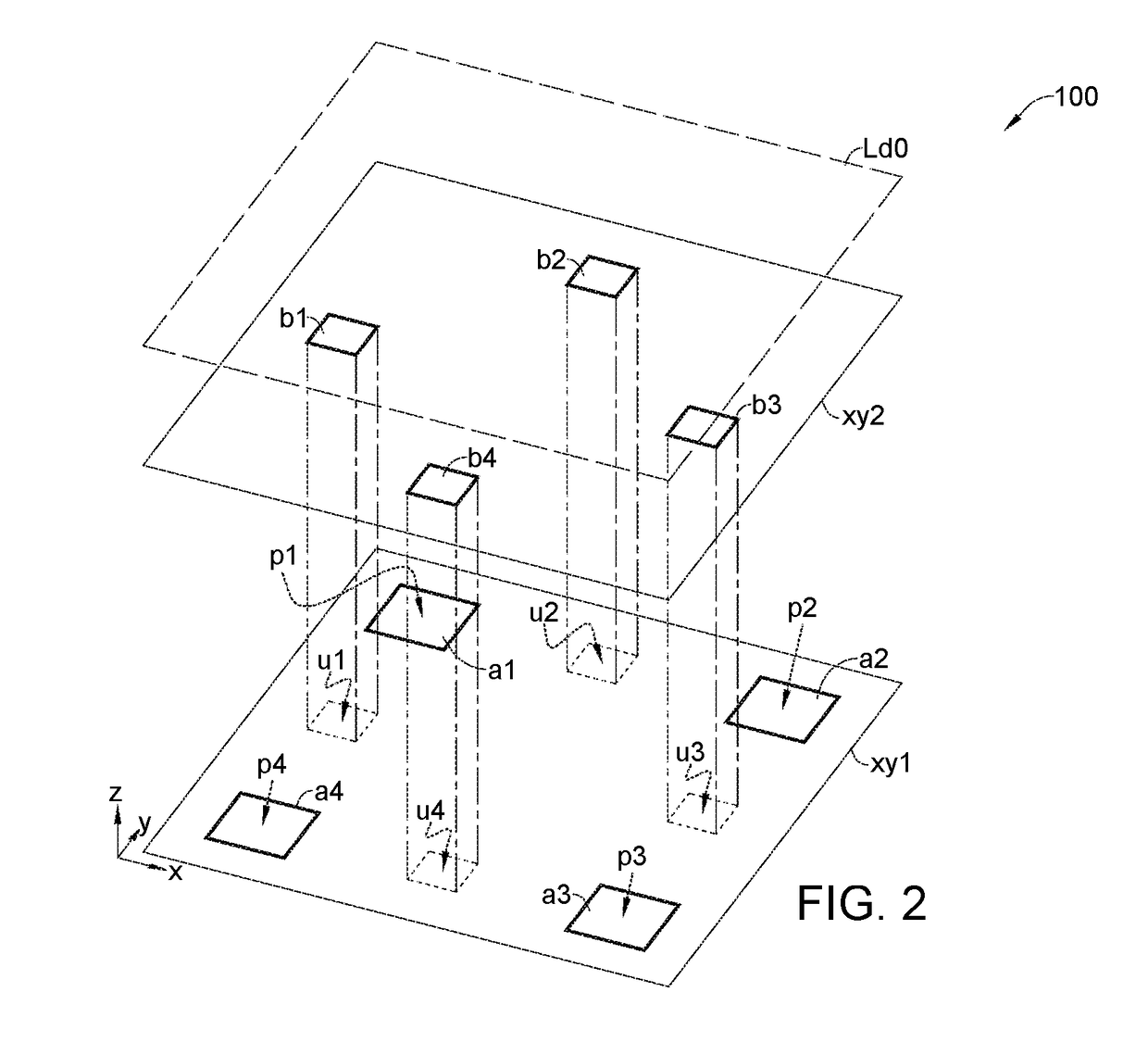
[0037]The low-band antennas a1 to a4 and the high-band antennas b1 to b4 may be disposed near the same surface or near different surfaces; for example, as shown in FIG. 2, the antennas a1 to a4 may be disposed near a surface xy1 (e.g., an x-y plane), the antenna...


PUM


Abstract

A multi-band antenna array includes a plurality of first antennas for resonating at a first band, and a plurality of second antennas for resonating at a second band. A frequency of the second band is higher than a frequency of the first band. Locations of the plurality of first antennas project to a plurality of grid-one positions on a surface; locations of the plurality of second antennas project to a plurality of grid-two positions on the surface. Among the grid-one positions, a second grid-one position is nearest to a first grid-one position by a first distance along a first direction. Among the grid-two positions, a first grid-two position and a second grid-two position are closest two to the first grid-one position. The first and second grid-two positions are separated by a second distance along a second direction; and, the first direction and the second direction are nonparallel.

Description

[0001]This application claims the benefit of U.S. Provisional application Ser. No. 62 / 558,376, filed Sep. 14, 2017, the subject matter of which is incorporated herein by reference.FIELD OF THE INVENTION[0002]The present invention relates to a multi-band antenna array, and more particularly, to a multi-band antenna array with antennas of different bands arranged adjacently along different directions for improving compactness.BACKGROUND OF THE INVENTION[0003]Antenna module is essential for devices which require wireless functionality, such as mobile phones which require mobile telecommunication. Modern advanced wireless functionality, such as 5G (fifth generation) mobile telecommunication, demands multi-band antenna module capable of signaling (transmitting and / or receiving) at multiple RF bands of different frequencies. In addition, limited form factor of wireless device constrains size of antenna module.SUMMARY OF THE INVENTION[0004]An objective of the invention is providing a multi...

Claims


Application Information

Patent Timeline
IPC IPC(8): H01Q21/30H01Q5/15H01Q5/28H01Q5/378
CPCH01Q21/30H01Q5/15H01Q5/28H01Q5/378H01Q5/20H01Q21/0006H01Q21/24H01Q1/246H01Q21/064H01Q21/065H01Q21/28H01Q25/001H01Q5/42H01Q1/242H01Q11/02H01Q1/1242
Inventor KAO, YEH-CHUNLIN, WUN-JIANTAI, CHEN-FANGHUANG, SHAO-YUYEH, SHIH-HUANG
Owner MEDIATEK INC
Why Eureka
Try Eureka