Cycle-type vehicle suspension provided with a resilient element for making it possible to obtain an optimal static compression curve, and optimized resilient element for such suspension

a resilient element and vehicle suspension technology, applied in resilient suspensions, vehicle springs, mechanical devices, etc., can solve the problems of preventing optimization throughout the entire available range of travel, excessive weight of suspension, and reducing the service life of suspensions

Active Publication Date: 2019-03-21
M OTION ENG
View PDF2 Cites 3 Cited by
  • Summary
  • Abstract
  • Description
  • Claims
  • Application Information

AI Technical Summary

Benefits of technology

[0017]This disclosure provides a suspension system that avoids drawbacks of the prior art and makes it possible to define a compression curve as close as possible to an ideal or optimal curve, without raising excessive weight, reliability, service life or overall dimensions issues.

Problems solved by technology

Bending springs have an almost linear static behavior, which generates bumping problems.
Compressively biased air springs have an exponential static behavior, which prevents optimization throughout the entire available range of travel.
Adding these parts results in an increase in the weight of the suspension, a greater number of parts and a greater complexity, which affects the reliability of the assembly and makes its implementation difficult.
However, adding so many extra parts (including connecting rods / rocker and the means for the connection thereof) results in excessive weight, reduced reliability, reduced service life, increased overall dimensions.
In addition, these elements consist of a large number of parts, some of which are moving (friction), require frequent maintenance and have reliability failures (leakage, friction, clearance, wear); andthe elastomers, foams and other soft materials that must be integrated into a mechanical assembly, enable a very limited travel, and define a non-optimal compression curve.

Method used


Image

  • Cycle-type vehicle suspension provided with a resilient element for making it possible to obtain an optimal static compression curve, and optimized resilient element for such suspension
  • Cycle-type vehicle suspension provided with a resilient element for making it possible to obtain an optimal static compression curve, and optimized resilient element for such suspension
  • Cycle-type vehicle suspension provided with a resilient element for making it possible to obtain an optimal static compression curve, and optimized resilient element for such suspension

Examples


Embodiment Construction

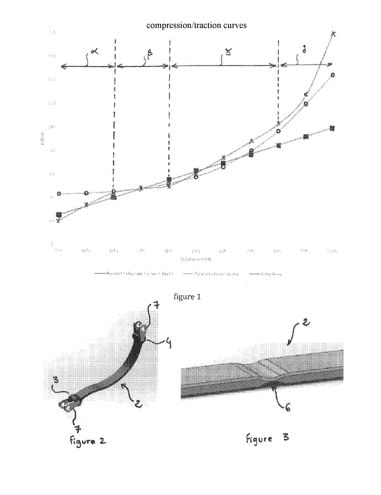
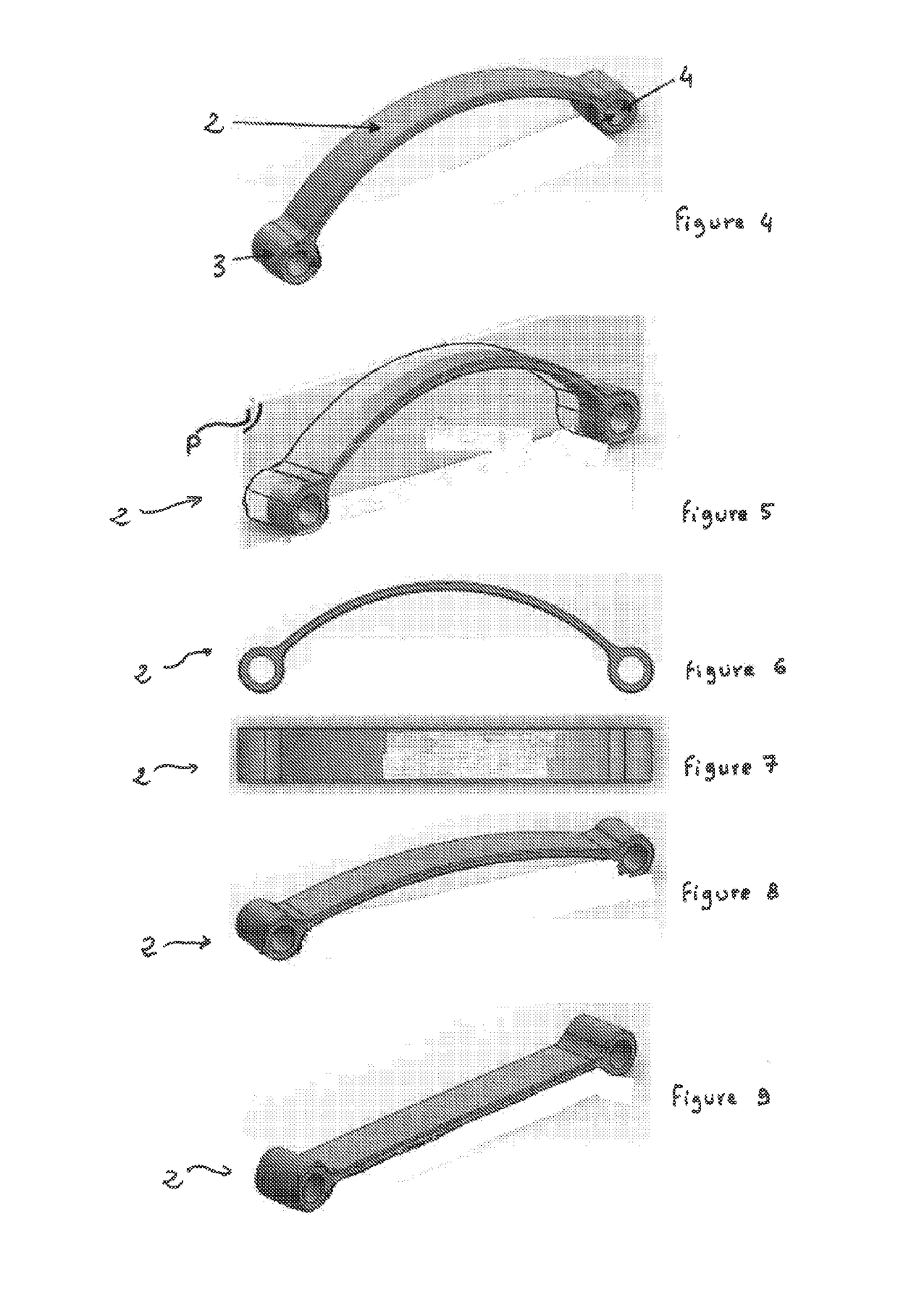
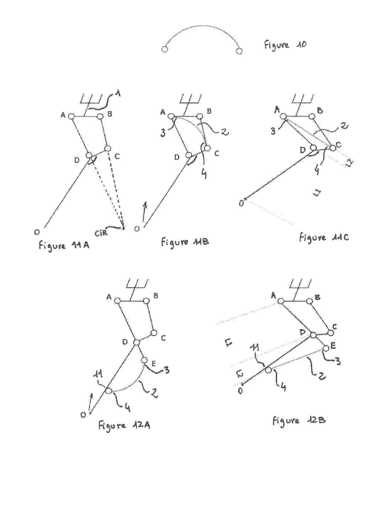
[0058]As shown in FIG. 11B, the disclosure relates to a suspension for a vehicle (a cycle in the examples shown) provided with a deformable blade stretched and biased between two points of the suspension separated from one another upon compression of the suspension, in order to define a compression curve close to an optimal compression / tension curve.

[0059]In the example shown in FIGS. 11A, 11B, 11C; 12A, and 12B, the front of the bicycle is on the left and the suspension consists of four elements connected together by four pivots A, B, C and D.

[0060]The four elements define:[0061]the upper plate AB: connected to the frame via the steering wheel swivel 1[0062]the lower arm ODC[0063]the upper arm AD[0064]the connecting rod BC

[0065]In addition, such suspension includes the axis of rotation of the front wheel 0.

[0066]The pivots A and B of the steering tube 1 are positioned on either side of the axis of the pivot connection between the steering tube 1 and the cycle frame (not shown).

[006...


PUM


Abstract

A vehicle wheel suspension system includes two relatively movable portions and a resilient blade that includes two means for mechanical connection to both relatively movable portions, respectively. The blade has a flexural resilience at least 100 times greater than the tensile resilience, and is resiliently deformable between: a resting state in which the blade has an inwardly curved profile, and a maximally extended state in which the blade has an elongate profile, the length of which corresponds to that of the neutral fiber of the blade, while passing through intermediate extension states in which the blade has profiles that are less and less inwardly curved. The suspension system is deformable between an initial state in which the relatively movable portions are in a close configuration and a compressed state in which the relatively movable portions are in a separated configuration and bias the blade.

Description

CROSS-REFERENCE TO RELATED APPLICATIONS[0001]This application is a national phase entry under 35 U.S.C. § 371 of International Patent Application PCT / FR2016 / 051560, filed Jun. 24, 2016, designating the United States of America and published as International Patent Publication WO 2016 / 207570 A2 on Dec. 29, 2016, which claims the benefit under Article 8 of the Patent Cooperation Treaty to French Patent Application Ser. No. 1555850, filed Jun. 25, 2015.TECHNICAL FIELD[0002]The technical field of the disclosure is that of vehicle suspensions, specifically, that of cycle suspensions such as those intended to be mounted on the cycle steering wheel, and / or mounted on the cycle rear wheel.BACKGROUND[0003]Vehicle and, specifically, cycle suspensions are used for smoothing the irregularities of the surface that the vehicle travels on by reducing the impact on the vehicle, by avoiding mechanical fatigue and excessive wear, by maintaining the contact between the wheels and the ground in spite o...

Claims


Application Information

Patent Timeline
Patent Type & Authority Applications(United States)
IPC IPC(8): B62K25/12
CPCB62K25/12B62K2201/06B60G11/02B60G2202/116F16F1/18B62K25/28
Inventor ALFANO, MATTHIEU
Owner M OTION ENG
Why Eureka
Try Eureka