Laterally unconstrained magnetic joint for tip-tilt and piston-tip-tilt mounts

a magnetic joint and lateral unconstrained technology, applied in the direction of instruments, mechanical equipment, photomechanical equipment, etc., can solve the problems of complex mounts, requiring precision machining, and conventional mounts that are not suitable for applications requiring rapid adjustment, and achieve simple and uniform design

Active Publication Date: 2019-03-21
LIGHT STEERING TECH LLC
View PDF2 Cites 8 Cited by
  • Summary
  • Abstract
  • Description
  • Claims
  • Application Information

AI Technical Summary

Benefits of technology

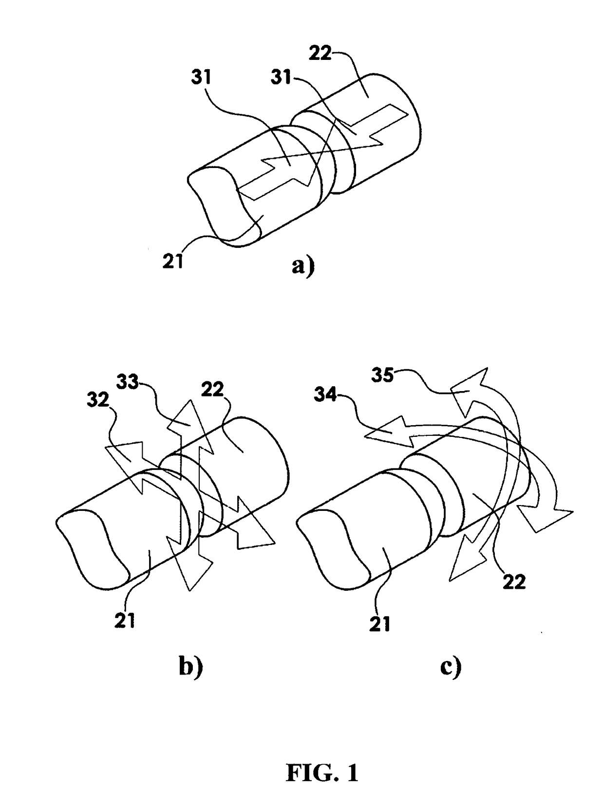
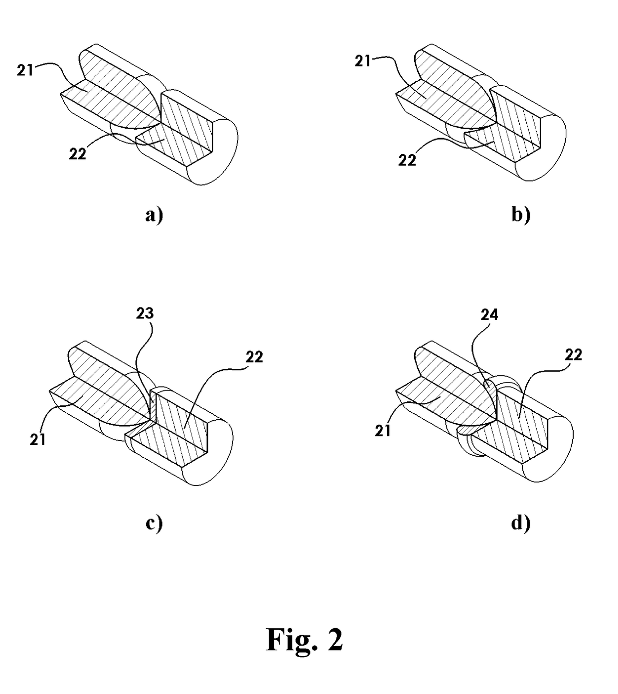
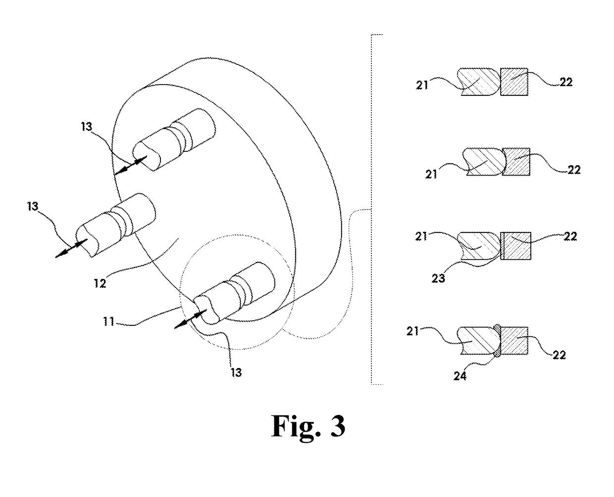
[0005]This invention comprises a novel method and apparatus for implementing a flexible magnetic joint and application of said flexible magnetic joint in tip-tilt and piston-tip-tilt optical mounts. The invention employs a magnetic joint which, in its basic embodiment, consists of two interfacing parts: one having a flat surface interfacing a convex surface of the other. One or both parts of the magnetic joint are made from permanent magnets which are magnetized along the axis of the joint, or one of the parts is made from a ferromagnetic material thus creating magnetic force attraction between the two parts.
[0006]Unlike conventional magnetic joints which utilize matching spherical surfaces and only allowing three rotational degree

Problems solved by technology

These mounts are often complex and require precision machining.
The optical element is usually mounted in a flame putting metal surfaces in close proximity to the retained optic, which can be undesirabl

Method used


Image

  • Laterally unconstrained magnetic joint for tip-tilt and piston-tip-tilt mounts
  • Laterally unconstrained magnetic joint for tip-tilt and piston-tip-tilt mounts
  • Laterally unconstrained magnetic joint for tip-tilt and piston-tip-tilt mounts

Examples


Embodiment Construction

[0012]The terminology used herein is for the purpose of describing particular embodiments only and is not intended to limit the invention. The term “and / or” includes any and all combinations of one or more of the associated listed items. The singular forms “a”, “an”, and “the” are intended to include the plural forms as well as singular forms, unless the context clearly indicates otherwise. It will be further understood that the terms “comprises” and / or “comprising”, when used in this specification, indicate the presence of stated features, elements, and / or components, but do not preclude the presence or addition of one or more other features, elements, components, and / or groups thereof.

[0013]The present disclosure is to be considered as an exemplification of the invention, and is not intended to limit the invention to the specific embodiments illustrated by figures or description below.

[0014]The present invention will now be described by referencing the appended figures representin...


PUM


Abstract

The subject of this invention is a laterally unconstrained magnetic joint and application of said joint in tip-tilt and piston-tip-tilt optical mounts. The laterally unconstrained magnetic joint in its basic embodiment comprises two interfacing parts: one having a flat surface interfacing a convex surface of the other, wherein one or both parts are made from permanent magnets that are magnetized along the axis of the joint, and the other of the said parts is made from a ferromagnetic material thus creating magnetic force attraction between the two parts. The resulting lack of lateral mechanical constraint between the two parts of the joint is utilized in tip-tilt mounts by decoupling an adjustor and/or actuator from the payload resulting in a simple, uniform design, while magnetic force provides retention sufficient for a wide variety of applications.

Description

FIELD OF THE INVENTION[0001]This disclosure relates generally to the mounting and positioning of optical components, and in particular to mounting and positioning of a mirror or other optical component requiring tip-tilt or piston-tip-tilt adjustments.BACKGROUND[0002]Optical systems require accuracy and stability in positioning of optical components and in many cases said components must have adjustment capabilities to achieve system performance. In particular, system alignment is often achieved via “pointing adjustment” of reflective components such as mirrors, using mounts with two rotational degrees of freedom around axes perpendicular to reflective surface normal, often termed “tip-tilt”.[0003]Conventional approaches for mirror mounting and adjustment include kinematic mounts, flexure mounts, and gimbal mounts. These mounts are often complex and require precision machining. The optical element is usually mounted in a flame putting metal surfaces in close proximity to the retaine...

Claims


Application Information

Patent Timeline
IPC IPC(8): G02B7/182G02B7/198G03F7/20F16C11/04
CPCG02B7/1828G02B7/198G03F7/70825F16C11/04F16C2226/18F16C2370/20G02B7/003
Inventor KRYLOV, VLADIMIR G.
Owner LIGHT STEERING TECH LLC
Why Eureka
Try Eureka