Pneumatic Tire

a pneumatic tire and tire body technology, applied in the field of pneumatic tires, can solve the problems of uneven wear, uneven wear, separation and chipping, etc., and achieve the effects of improving uneven wear resistance performance, reducing friction, and improving rigidity

Active Publication Date: 2019-03-28
THE YOKOHAMA RUBBER CO LTD
View PDF0 Cites 3 Cited by
  • Summary
  • Abstract
  • Description
  • Claims
  • Application Information

AI Technical Summary

Benefits of technology

[0038]According to the pneumatic tire, the aspect ratio of the tire circumferential direction dimension L of the block and the tire lateral direction dimension We is configured to be in the range described above to make it easier for the block to have a difference in rigidity.
[0039]The present technology can provide improved uneven wear resistance performance while maintaining durability performance.
[0040]The present technology can provide improved uneven wear resistance performance even with a configuration including a circumferential belt.

Problems solved by technology

In a typical tire, uneven wear is caused by high amounts of pressure acting on the tire when it comes into contact with the ground.
This may lead to separation and chipping.
This causes uneven wear.
As a result, the effect of maintaining durability performance is great.
Thus, the effect of maintaining durability is great.
As a result, the effect of maintaining durability is great.
As a result, the effect of improving uneven wear resistance performance is great.

Method used


Image

  • Pneumatic Tire
  • Pneumatic Tire
  • Pneumatic Tire

Examples


first embodiment

[0061]A first embodiment of the present technology is described in detail below with reference to the drawings. However, the present technology is not limited by the first embodiment. Constituents of the first embodiment include elements that are essentially identical or that can be substituted or easily conceived by a person skilled in the art. Furthermore, the modified examples described for the first embodiment can be combined as desired within the scope apparent to those skilled in the art.

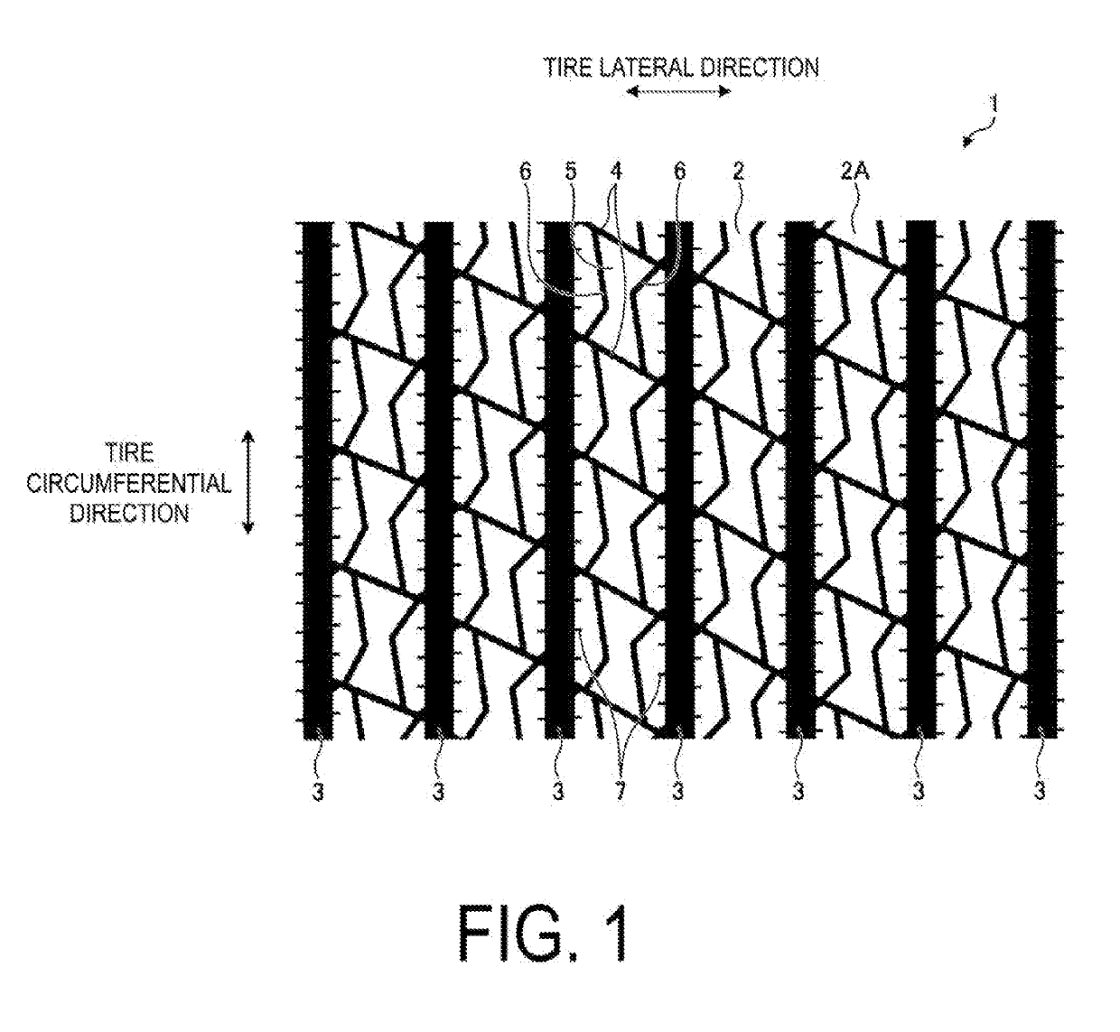
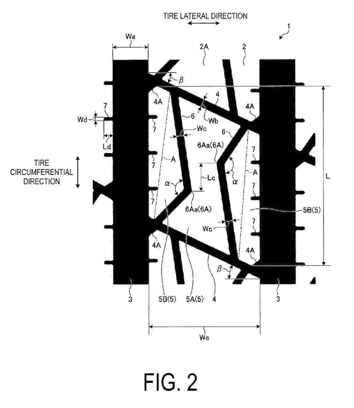
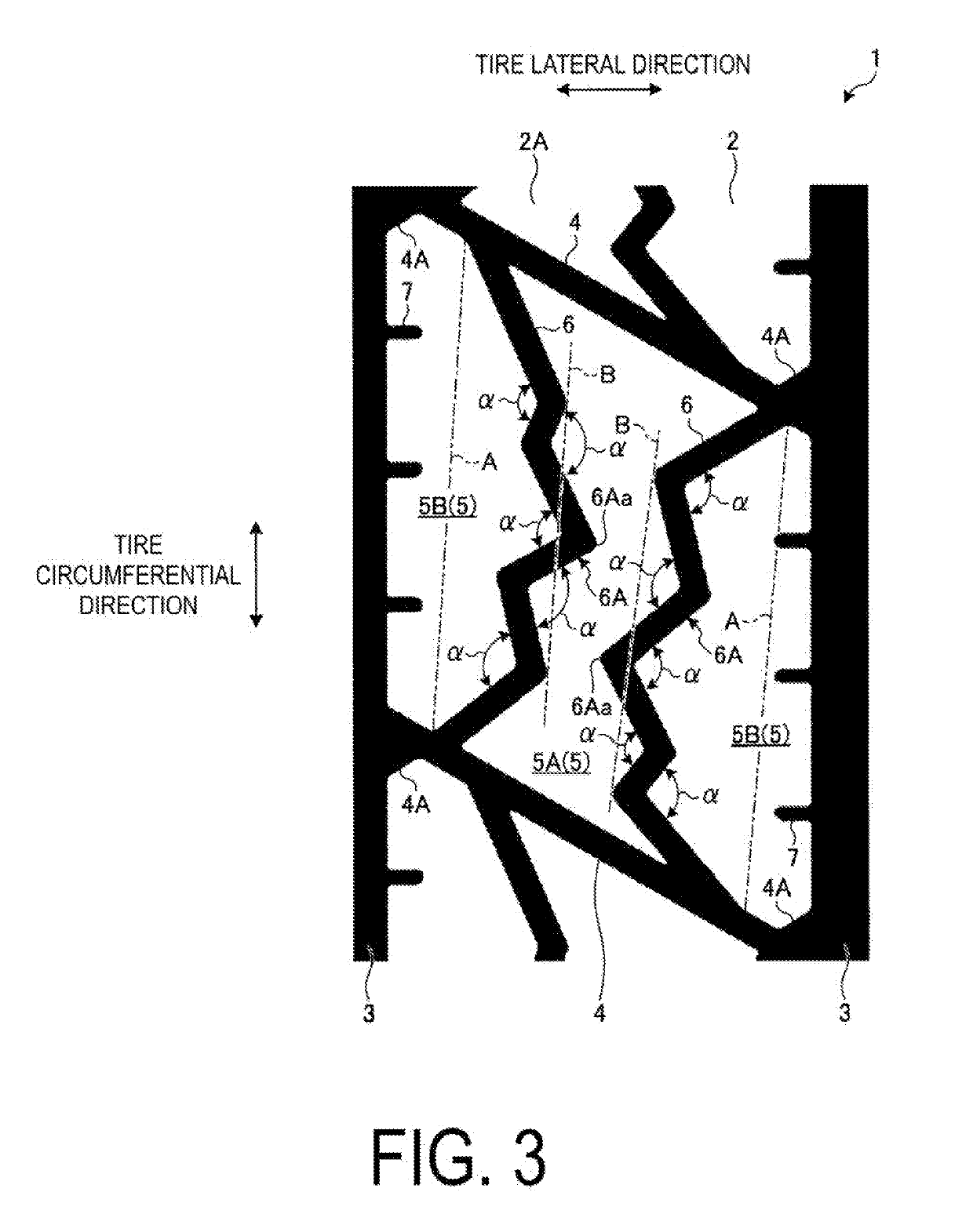
[0062]FIG. 1 is a plan view of a tread portion of a pneumatic tire according to the first embodiment. FIG. 2 is an enlarged view of the tread portion of the pneumatic tire according to the first embodiment. FIG. 3 is an enlarged view of another tread portion of the pneumatic tire according to the first embodiment. FIG. 4 is an enlarged view of another tread portion of the pneumatic tire according to the first embodiment. FIG. 5 is an enlarged cross-sectional view of the tread portion of the pn...

first examples

[0090]For the first examples, performance tests for uneven wear resistance performance and durability performance were performed on a plurality of types of test tires of different conditions (see FIGS. 7 and 8).

[0091]In the performance tests, pneumatic tires (heavy duty pneumatic tires) having a tire size of 445 / 50R22.5 were mounted on regular rims, inflated to the regular internal pressure, and mounted on the trailer axle of a test vehicle (2-D·D vehicle (i.e., three axle vehicle with single tire steering axle and tandem dual tire drive axle).

[0092]Here, “regular rim” refers to a “standard rim” defined by the Japan Automobile Tyre Manufacturers Association Inc. (JATMA), a “Design Rim” defined by the Tire and Rim Association, Inc. (TRA), or a “Measuring Rim” defined by the European Tyre and Rim Technical Organisation (ETRTO). “Regular internal pressure” refers to a “maximum air pressure” defined by JATMA, the maximum value in “TIRE LOAD LIMITS AT VARIOUS COLD INFLATION PRESSURES” de...

second embodiment

[0097]A second embodiment of the present technology is described in detail below with reference to the drawings. However, the present technology is not limited by the second embodiment. Constituents of the second embodiment include elements that are essentially identical or that can be substituted or easily conceived by a person skilled in the art. Furthermore, the modified examples described in the second embodiment can be combined as desired within the scope apparent to one skilled in the art.

[0098]FIG. 9 is a meridian cross-sectional view of a portion of a pneumatic tire according to the second embodiment. FIG. 10 is a plan view of a tread portion of the pneumatic tire according to the second embodiment. FIG. 11 is an enlarged plan view of the tread portion of the pneumatic tire according to the second embodiment. FIGS. 12 and 13 are enlarged cross-sectional views of the tread portion of the pneumatic tire according to the second embodiment.

[0099]Hereinafter, “tire radial directi...


PUM


Abstract

A pneumatic tire includes circumferential grooves aligned in a lateral direction and extending in a circumferential direction, lateral grooves aligned in the circumferential direction and extending to cross the circumferential direction, communicating at ends with the circumferential grooves and defining a block-shaped land portion between the circumferential grooves, two narrow grooves aligned in the lateral direction and extending in the circumferential direction, communicating at ends with a lateral groove and dividing the land portion defined by each of the circumferential grooves and each of the lateral grooves into small land portions, the narrow grooves having a smaller groove width than the circumferential grooves and being formed with a bent portion in an intermediate portion, the bent portion being disposed inward in the lateral direction, and bend points of the bent portions being disposed at positions offset from one another in the circumferential direction.

Description

TECHNICAL FIELD[0001]The present technology relates to a pneumatic tire.BACKGROUND ART[0002]In a typical tire, uneven wear is caused by high amounts of pressure acting on the tire when it comes into contact with the ground. Thus, ground contact pressure needs to be appropriately alleviated.[0003]A known pneumatic tire, for example the pneumatic tire described in Japan Patent Publication No. 2003-182315, is designed to improve steering stability on snow in a travel-worn stage without decreasing dry steering stability. This pneumatic tire includes, in a road contact surface portion of a tread portion, a plurality of main grooves extending in a circumferential direction, and a block defined by lateral grooves that cross the main grooves. The block includes sipes and a pair of acute angle block corner portions on opposite sides in the circumferential direction. The blocks further include a pair of small blocks defined by the pair of acute angle block corner portions and two of the sipes...

Claims


Application Information

Patent Timeline
Patent Type & Authority Applications(United States)
IPC IPC(8): B60C11/12B60C11/03
CPCB60C11/1236B60C11/1204B60C11/0306B60C11/1259B60C11/1272B60C2200/06B60C2011/1245B60C11/03B60C9/18B60C11/12B60C2011/0341B60C2011/1209B60C11/125B60C2011/0344B60C2011/0372B60C11/0302B60C11/1281B60C11/04B60C2011/0381B60C11/1384B60C2011/036B60C2011/0348
Inventor TAKATA, MINA
Owner THE YOKOHAMA RUBBER CO LTD
Why Eureka
Try Eureka