Power supply system

a power supply system and power supply technology, applied in the field of power supply systems, can solve the problems of unstable operation, power supply device may not support the sudden change of load current, inability to quickly activate, etc., and achieve the effect of reducing the number of converters deactivated

Active Publication Date: 2019-03-28
MURATA MFG CO LTD
View PDF0 Cites 5 Cited by
  • Summary
  • Abstract
  • Description
  • Claims
  • Application Information

AI Technical Summary

Benefits of technology

[0022]In this configuration, the number of converters deactivated can be minimized, and excessive discharging from the power storage device can be suppressed.
[0023]According to the exemplary embodiments, one or more converters are deactivated during light-load conditions, the load factor of a converter continuing its operation is increased, and it is enabled to operate in a higher efficiency range. This can reduce the loss and enhance the power conversion efficiency. A stable voltage can be supplied to the load. In addition, if the load suddenly changes to a heavy state, the power storage device assists supplying power until the inactive converter is activated, and the effects of deactivation of the converter, for example, decrease in voltage supplied to the load, can be suppressed.

Problems solved by technology

If the load suddenly changes from light to heavy in the state where one or more power supply units are inactive, they may be unable to be quickly activated, and the power supply device may fail to support the suddenly changing load current.
In particular, if the load is an information processing system apparatus, such as a server, the voltage decrease may cause unstable operations.
For this reason, the power supply device in Patent Document 1 is not suited for information processing system apparatuses, such as servers.

Method used


Image

  • Power supply system
  • Power supply system
  • Power supply system

Examples


first exemplary embodiment

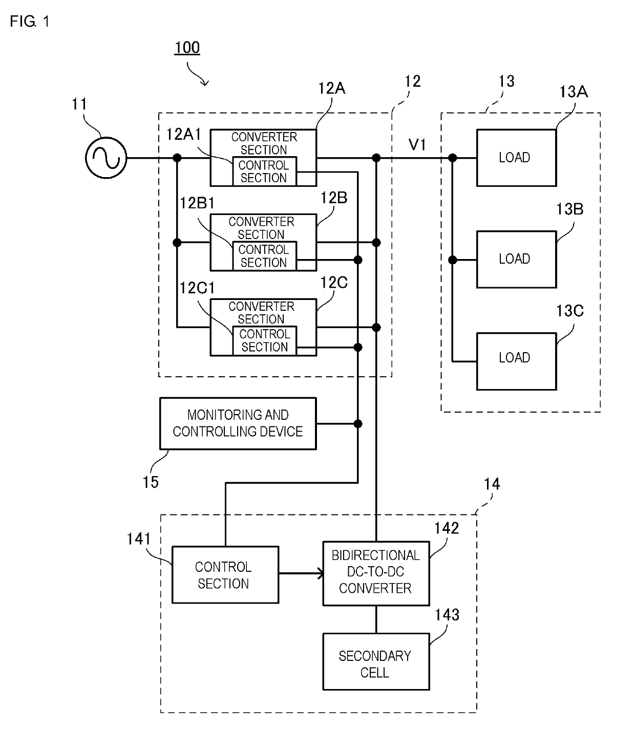
[0033]FIG. 1 is a block diagram of a power supply system 100 according to the present embodiment.

[0034]The power supply system 100 includes a commercial power supply 11, a converter unit 12, a load 13A, a load 13B, a load 13C, a battery module 14, and a monitoring and controlling device 15.

[0035]One example of the loads 13A, 13B, and 13C may be a blade server and be housed in a casing. The loads 13A, 13B, and 13C are connected in parallel and are connected to the converter unit 12. The loads 13A, 13B, and 13C receive power from the converter unit 12. Hereinafter, the loads 13A, 13B, and 13C are expressed as load 13.

[0036]The converter unit 12 includes a converter section 12A, a converter section 12B, and a converter section 12C. Each of the converter sections 12A, 12B, and 12C includes an AC-to-DC converter. The converter sections 12A, 12B, and 12C are connected in parallel between the commercial power supply 11 and load 13. The converter sections 12A, 12B, and 12C include control s...

second exemplary embodiment

[0066]The present embodiment differs from the first embodiment in the method of starting driving an inactive converter section.

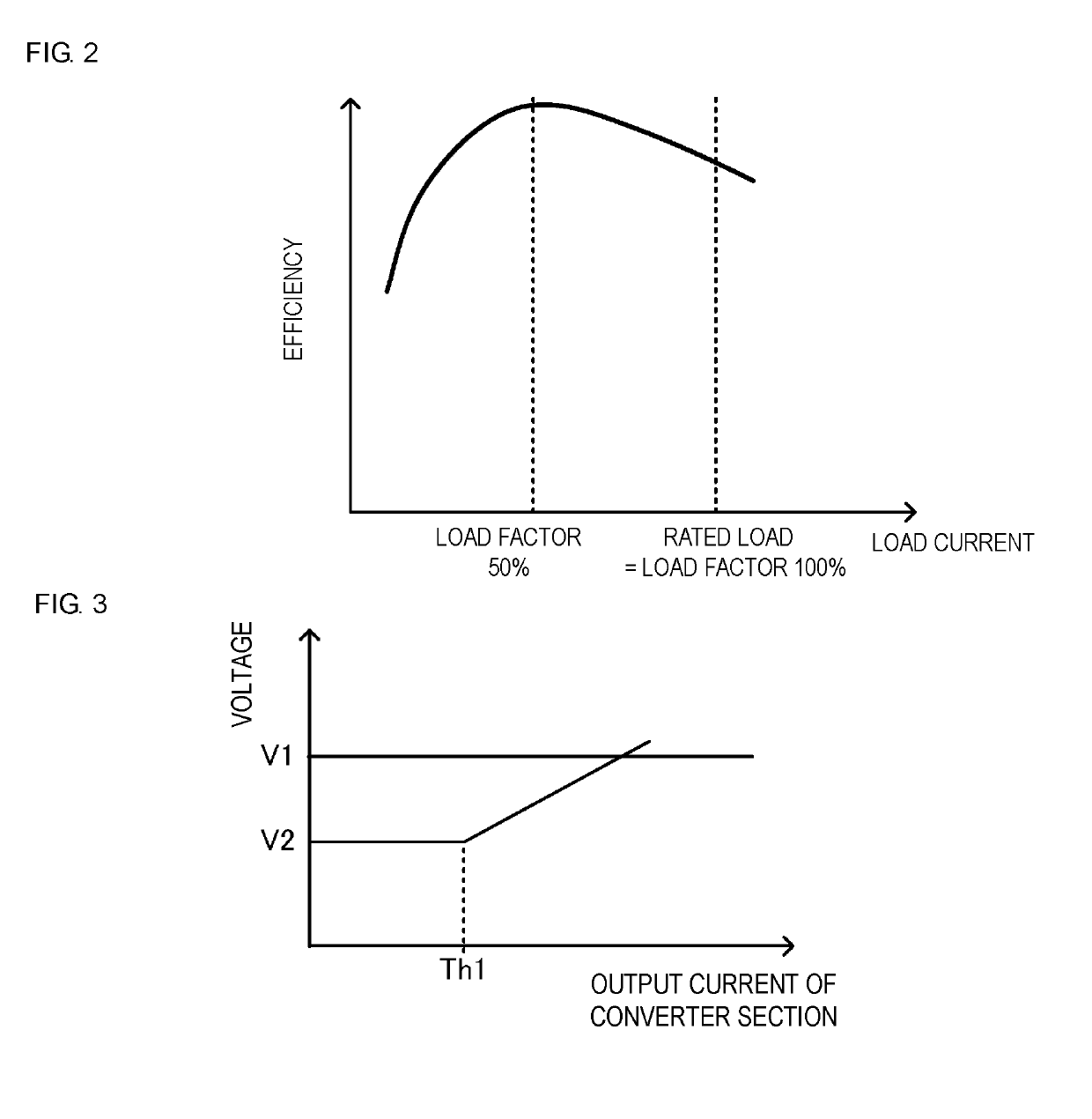
[0067]FIG. 7 illustrates output voltage characteristics of the bidirectional DC-to-DC converter 142. The output voltage characteristics illustrated in FIG. 7 correspond to each of the converter sections 12A, 12B, and 12C. The voltage characteristics illustrated in FIG. 7 indicate target values of the voltage output by the bidirectional DC-to-DC converter 142.

[0068]The control section 141 controls the bidirectional DC-to-DC converter 142 such that it outputs the constant voltage V2 independently of the output current value included in the current sharing signal. The voltage V2 is the output voltage of the battery module. It is lower than the constant voltage V1, which is normally output from the converter sections 12A, 12B, and 12C.

[0069]Each of the converter sections 12A, 12B, and 12C is subjected to constant-voltage control at which it outputs the constant ...

third exemplary embodiment

[0079]A power supply system according to a third embodiment is described below.

[0080]FIG. 9 is a block diagram of a power supply system 101 according to the third exemplary embodiment.

[0081]The control section 141 in the battery module 14 in the first and second embodiments receives a current sharing signal and performs charging and discharging control for the secondary cell 143. In contrast, in the present embodiment, the control section 141 in the battery module 14 does not receive a current sharing signal, performs switching control for the bidirectional DC-to-DC converter 142, and performs discharging control for the secondary cell 143. That is, in the present embodiment, after the output voltage of the converter section decreases, the battery module 14 assists supplying power.

[0082]The monitoring and controlling device 15 receives an output current signal from an output current detection section 144 and detects discharging from the battery module 14. The occurrence of the outpu...


PUM


Abstract

A power supply system that includes a converter unit, a battery module connected in parallel to the converter unit and configured to supply power to a load, and a monitoring and controlling device configured to deactivate one or more of converter sections and to start driving the inactive converter section(s) in accordance with a light or heavy state of the load. When the output voltage of the battery module becomes higher than the output voltage of the converter unit when one or more of the converter sections are inactive, the output voltage of the battery module is supplied to the load. The monitoring and controlling device starts driving the inactive converter section(s) by the time the output voltage of the battery module exceeds the output voltage of the converter unit.

Description

CROSS REFERENCE TO RELATED APPLICATIONS[0001]The present application is a continuation of PCT / JP2017 / 017776 filed May 11, 2017, which claims priority to Japanese Patent Application No. 2016-110981, filed Jun. 2, 2016, the entire contents of each of which are incorporated herein by reference.TECHNICAL FIELD[0002]The present disclosure relates to a power supply system that assists supplying voltage to a load.BACKGROUND[0003]Patent Document 1 (identified below) discloses a power supply device that includes a plurality of power supply units connected in parallel and that controls the number of operating power supply units in accordance with a load current. This power supply device can maintain high power supply conversion efficiency even in light-load states and achieve energy conservation by preventing a decrease in power conversion efficiency in light-load conditions.[0004]Patent Document 1: Japanese Unexamined Patent Application Publication No. 2012-210013.[0005]The power supply devi...

Claims


Application Information

Patent Timeline
Patent Type & Authority Applications(United States)
IPC IPC(8): G06F1/3296G05F1/46H02M3/04
CPCG06F1/3296G05F1/465H02M3/04H02M7/12
Inventor MORI, MICHIYA
Owner MURATA MFG CO LTD
Why Eureka
Try Eureka