Check patentability & draft patents in minutes with Patsnap Eureka AI!

Sensor defect diagnostic circuit

a technology of defect detection and sensor, applied in the direction of instruments, galvano-magnetic hall-effect devices, galvano-magnetic devices, etc., can solve the problems of false positive, material defects affecting the accuracy of sensors, offset bias or symmetry of sensor response, etc., to improve diagnostic capability.

Active Publication Date: 2019-04-11
MELEXIS BULGARIA LTD
View PDF3 Cites 3 Cited by
  • Summary
  • Abstract
  • Description
  • Claims
  • Application Information

AI Technical Summary

Benefits of technology

The present invention provides sensor devices that can diagnose and detect faults in real-time, using smaller and less expensive circuits. This helps to prevent sensor malfunctions and ensure accurate readings.

Problems solved by technology

Moreover, devices can fail over time for similar reasons.
Furthermore, the materials from which sensors are made can have defects that affect the accuracy, offset bias or symmetry of the sensor's response.
However, these approaches and others similar to them do not necessarily operate the sensor system under critical operating conditions and can therefore provide a false positive result.
Moreover, field sensors are subject to faults or defects in the sensor materials leading to incorrect field measurements.

Method used


Image

  • Sensor defect diagnostic circuit
  • Sensor defect diagnostic circuit
  • Sensor defect diagnostic circuit

Examples


Embodiment Construction

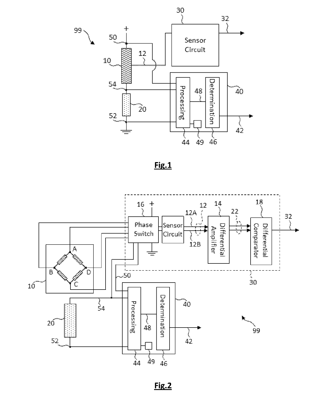
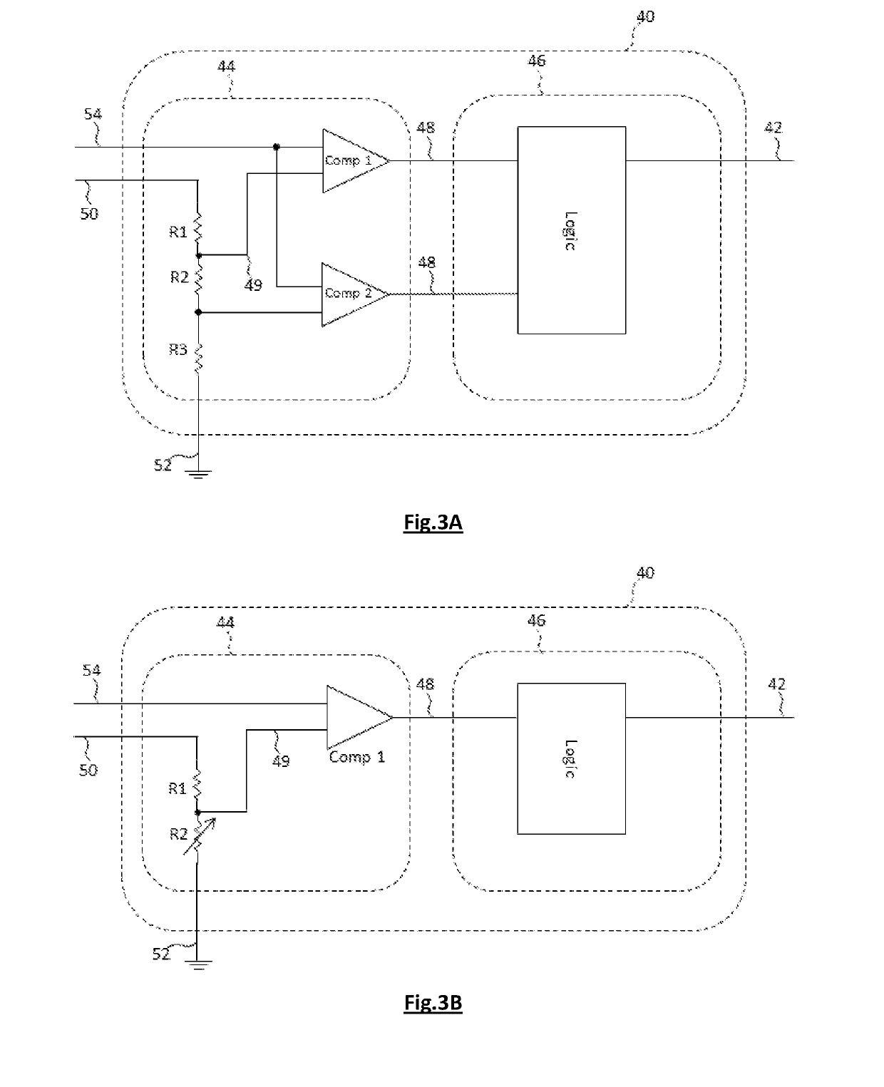
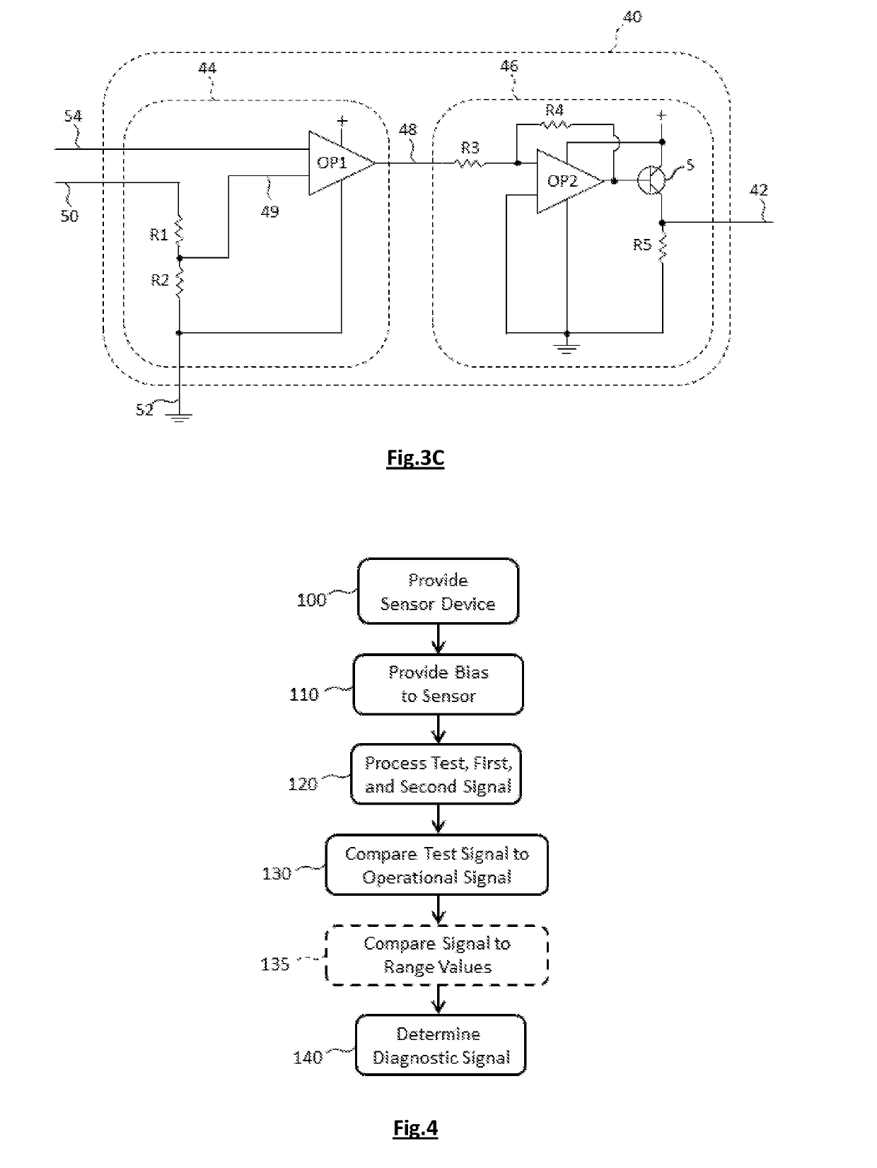
[0037]The present invention will be described with respect to particular embodiments and with reference to certain drawings but the invention is not limited thereto but only by the claims. The features and advantages of the present disclosure will become more apparent from the detailed description set forth below when taken in conjunction with the drawings, in which like reference characters identify corresponding elements throughout. In the drawings, like reference numbers generally indicate identical, functionally similar, and / or structurally similar elements. The figures are not drawn to scale since the variation in size of various elements in the Figures is too great to permit depiction to scale.

[0038]Furthermore, the terms first, second and the like in the description and in the claims, are used for distinguishing between similar elements and not necessarily for describing a sequence, either temporally, spatially, in ranking or in any other manner. It is to be understood that t...


PUM


Abstract

A sensor device comprises a sensor connected to a first signal and responsive to an external field to produce a sensor signal, a test device connected to a second signal and electrically connected in series with the sensor by an electrical test connection providing a test signal, and a monitor circuit electrically connected to the first, second and test signals. The monitor circuit comprises a processing circuit and a determination circuit. The processing circuit is responsive to the test signal and a predetermined processing value to form a processing output signal. The determination circuit is responsive to the processing output signal to determine a diagnostic signal. A sensor circuit responsive to the sensor signal provides a sensor device signal responsive to the external field.

Description

FIELD OF THE INVENTION[0001]The present invention is generally related to the field of integrated sensor diagnostic structures, circuits and methods.BACKGROUND OF THE INVENTION[0002]Sensors are widely used in electronic devices to measure attributes of the environment and report a measured sensor value. In particular, magnetic sensors are used to measure magnetic fields, for example in transportation systems such as automobiles. Magnetic sensors can incorporate Hall-effect sensors that generate an output voltage proportional to an applied magnetic field or magneto-resistive materials whose electrical resistance changes in response to an external magnetic field.[0003]In many applications, it is desirable that sensors are small and are integrated with an electronic processing circuit so as to reduce the overall sensor system size and provide improved measurements and integration into external electronic systems. For example, US2016 / 299200 describes a Hall-effect magnetic sensor for me...

Claims


Application Information

Patent Timeline
Patent Type & Authority Applications(United States)
IPC IPC(8): G01R31/3185G01R31/3187G01R33/07H01L43/04H01L43/06
CPCG01R31/318511G01R31/3187G01R33/07H01L43/04H01L43/065G01R33/0035G01D18/00G01D21/00H10N52/80H10N52/101
Inventor MARINOV PEEV, RUMENGEORGIEV GAYDOV, STOYAN
Owner MELEXIS BULGARIA LTD
Features
  • R&D
  • Intellectual Property
  • Life Sciences
  • Materials
  • Tech Scout
  • Unparalleled Data Quality
  • Higher Quality Content
  • 60% Fewer Hallucinations
Learn More