Eureka AIR delivers breakthrough ideas for toughest innovation challenges, trusted by R&D personnel around the world.

Heat Capacitive Component Carrier and Method to Produce Said Component Carrier

Active Publication Date: 2019-04-11
AT & S AUSTRIA TECH & SYSTTECHN AKTIENGES
View PDF1 Cites 14 Cited by
  • Summary
  • Abstract
  • Description
  • Claims
  • Application Information

AI Technical Summary

Benefits of technology

The invention is a component carrier that has a heat-passage component, like a heat-generating or heat-absorbing component, mounted on its surface or embedded within its layers. It also includes a latent-heat storage unit with a phase-change material that is integrated within the component carrier's laminated build-up and directly thermoconductively coupled with the heat-passage component. This helps to manage the heat generated by the component and keep the component carrier cool.

Problems solved by technology

However, such applications are not without their limitations and problems.
Disadvantageously the open recess has to be sealed afterwards to avoid leakage of the PCM material.
Another disadvantage of said embodiment has to be pointed out: When the open recess in the quasi-finished printed circuit board is later on in the assembly process filled with a PCM material, that will inevitably result in unwanted air gaps or air pockets between the PCM material and the PCB.
Especially when PCM materials with a solid cover or solid housing, like ceramics or epoxy resin composites filled with PCM, are applied, unwanted air gaps between the solid PCM housing and the recess walls of the PCB will remain, and will influence negatively the thermal flow or heat transfer, respectively.
The heat producing photo emissive device is not in direct contact with the PCM module, which is a significant disadvantage of this specific embodiment.
The aforementioned technical designs however have at least the drawback that the PCM material is not in direct thermal contact with hot spots of the heat-releasing components and / or structures, what is especially of disadvantageous when these components or structures are embedded within a multi-layered printed circuit board structure.
Unfavourably, PCM material that is arranged in external layers outside of the PCB or in open recesses of the PCB but apart from said heat-releasing components and / or structures can store and dissipate off-heat only to a limited extent due to less thermal conduction or higher heat transfer resistance, respectively.
As the base substrate is arranged layer-wise, this embodiment has at least the disadvantage that the micro-encapsulated PCM material is not in direct contact with the semiconductor device.
Furthermore, the layer-wise arrangement of the base substrate layer has the drawback that manufacture of through-connections like copper vias is not possible.
By drilling the base substrate layer, some of the encapsulated filler particles probably will be damaged and the encapsulated PCM material will be opened, what results in PCM spillage and undesired cavities within the drilling hole's walls.

Method used


Image

  • Heat Capacitive Component Carrier and Method to Produce Said Component Carrier
  • Heat Capacitive Component Carrier and Method to Produce Said Component Carrier
  • Heat Capacitive Component Carrier and Method to Produce Said Component Carrier

Examples


first embodiment

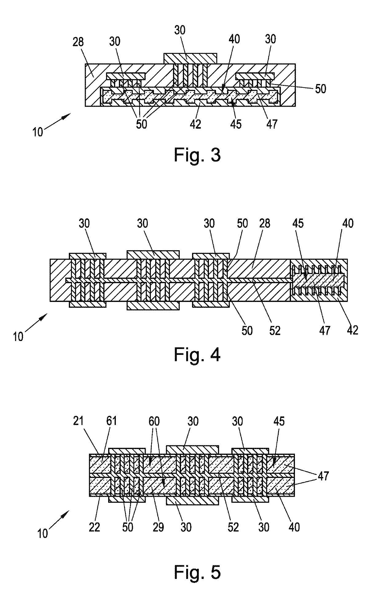
[0135]FIG. 3 depicts in a cross-sectional side view a detail of a component carrier 10 according to the invention. Here a possible printed circuit board build-up is shown with a latent-heat storage unit 40 comprising a phase-change material 45. Here a copper structure is built as cooling body 42 to enclose the phase-change material 45, which is for example microencapsulated phase-change material 47. The cooling body 42 is designed as heat-exchanger with an enlarged inner surface. The latent-heat storage unit 40 with its copper structure 42 is directly connected with several thermal vias 50 to hot-spots of heat-passage components 30 that are embedded within not explicitly shown layers 20 like outside surface layers 21, 22 and inner layers 23, 24 of the component carrier 10. Depending on the layer design, there may be layers 20 made of conducting material and also layers 20 made of insulating pre-preg material 28. Another heat-passage component 30 is surface-mounted on top of the prin...

second embodiment

[0136]FIG. 4 shows in a cross-sectional side view a detail of a component carrier 10 according to the invention. Here within an intermediate printed circuit board product the hot-spots of the heat-passage components 30 are thermally connected via thermal vias 50 to a central heat pipe 52. The heat pipe 52 however is directly connected to a latent-heat storage unit 40 that has a cooling body 42 made of a copper structure and is filled with phase-change material 45 which is here microencapsulated phase-change material 47. The cooling body 42 is designed as heat-exchanger with an enlarged inner surface to enhance the heat conduct of the stored latent heat to quickly reverse the phase-change process and to reduce temperature of the phase-change material 47.

third embodiment

[0137]FIG. 5 depicts in a cross-sectional side view a detail of a component carrier 10 according to the invention. Here the heat-passage components 30 are surface-mounted on an intermediate printed circuit board product, which comprises a matrix material carrier 60 as latent-heat storage unit 40 made of a foam material 29. The phase-change material 45 which is here microencapsulated phase-change material 47 is arranged within the cavities 61 of the matrix material carrier 60. Hot-spots of the heat-passage components 30 are thermally connected via thermal vias 50 to a central heat pipe 52 that runs through the matrix material carrier 60 filled with PCM 45.


PUM


Abstract

The invention refers to a component carrier realized as a printed circuit board, an intermediate printed circuit board product or an IC-substrate, comprising at least one heat-passage component, said at least one heat-passage component being realized in form of a heat-generating or a heat-absorbing component that is mounted on an outside surface layer or is embedded within at least one inner layer of the component carrier, and further comprising at least one latent-heat storage unit with a phase-change material. The phase-change material is arranged within at least one cavity and integrated within a laminated build-up of the component carrier and is directly thermoconductively coupled with the at least one heat-passage component. The invention also refers to a method for producing said component carrier.

Description

CROSS REFERENCE TO RELATED APPLICATIONS[0001]This application is a U.S. National Stage of PCT Application No. PCT / EP2017 / 060071 filed Apr. 27, 2017, which claims priority to European Application No. 16167266.2 filed Apr. 27, 2016, the disclosures of which are incorporated by reference herein in their entirety.FIELD OF THE INVENTION[0002]The present disclosure generally relates to component carriers such as printed circuit boards. More specifically the invention relates to systems and methods of a heat capacitive component carrier.[0003]The invention refers to a component carrier, realized as a printed circuit board, an intermediate printed circuit board product or an IC-substrate, comprising at least one heat-passage component, said at least one heat-passage component being realized in form of a heat-generating or a heat-absorbing component that is mounted on an outside surface layer or is embedded within at least one inner layer of the component carrier, and further comprising at l...

Claims


Application Information

Patent Timeline
IPC IPC(8): H05K1/02H01L23/427H01L23/38H01L21/48H05K3/22H05K3/40F28D20/02
CPCH05K1/0206H01L23/427H01L23/38H01L21/4846H05K3/22H05K3/4038F28D20/023H05K2201/064H05K2201/10219H05K1/0203F28D15/0233H01L23/3677H01L23/3736Y02E60/14
Inventor SILVANO DE SOUSA, JONATHAN
Owner AT & S AUSTRIA TECH & SYSTTECHN AKTIENGES
Why Eureka
Eureka Blog
Learn More