Multimode roic pixel with laser range finding (LRF) capability

a laser range finding and multi-mode technology, applied in the field of optical sensors, can solve the problems of increasing power consumption, increasing power consumption, and reducing the pixel area and power consumption

Active Publication Date: 2019-04-18
SENSORS UNLTD
View PDF0 Cites 8 Cited by
  • Summary
  • Abstract
  • Description
  • Claims
  • Application Information

AI Technical Summary

Benefits of technology

[0014]In addition, in embodiments, the FPA further includes at least one control circuit that receives an input control signal and controls the bias level of the bias signal applied to each of the pixels of the array of active pixels. In embodiments, the control signal is based on user input. Furthermore, in embodiments, the pixels of the array of active pixels are structurally uniform.*.

Problems solved by technology

Systems that require multiple sensors pose challenges for integration into a single optical sensor or focal plane array due to size and complexity considerations.
However, increasing the bandwidth of the ROIC circuitry to accommodate TOF determination needs typically requires additional circuit elements per pixel as well as increased power consumption, both of which buck trends decreasing pixel area and power consumption.
Moreover, additional pixel circuitry used for implementation of the voltage-based ramp technique can affect performance of different imaging modes and / or increase pixel size.

Method used


Image

  • Multimode roic pixel with laser range finding (LRF) capability
  • Multimode roic pixel with laser range finding (LRF) capability
  • Multimode roic pixel with laser range finding (LRF) capability

Examples


Embodiment Construction

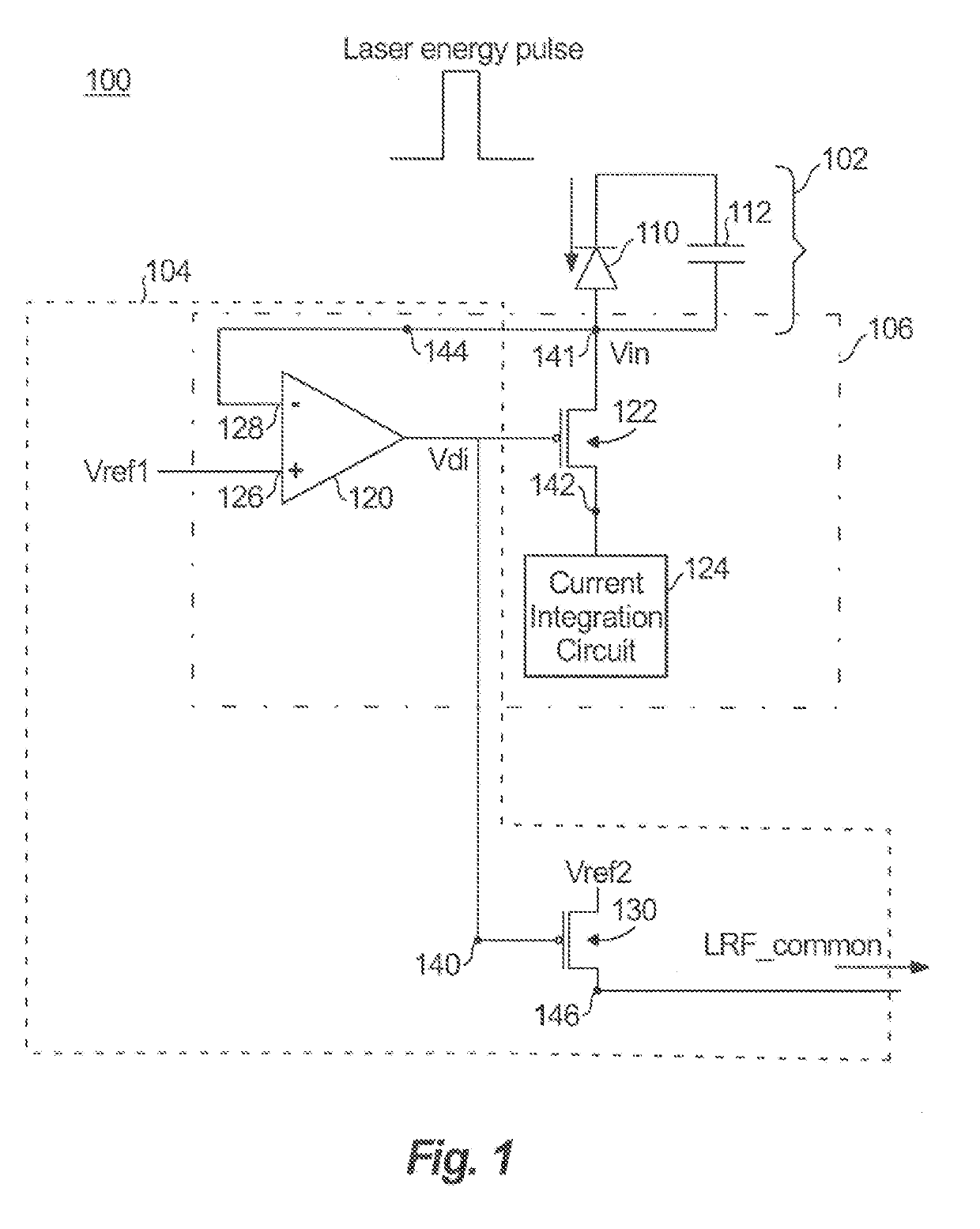
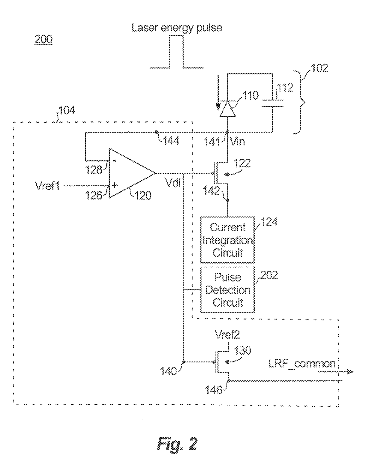
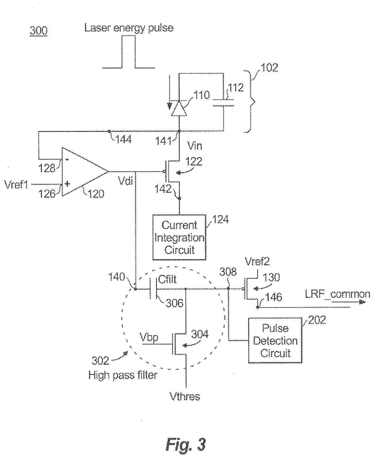
[0025]Reference will now be made to the drawings wherein like reference numerals identify similar structural features or aspects of the subject disclosure. For purposes of explanation and illustration, and not limitation, a schematic diagram of an exemplary embodiment of an example multimode LRF pixel for multimode sensing in accordance with the disclosure is shown in FIG. 1 and is designated generally by reference character 100. Other embodiments of a multimode LRF pixel in accordance with the disclosure, or aspects thereof, are provided in FIGS. 2-7, as will be described.

[0026]As described in greater detail below, the multimode LRF pixel 100 is included in a multimode focal plane (FPA) array that has multimode capabilities for both laser range finding (LRF) and imaging. Each multimode LRF pixel 100 has LRF capabilities, meaning the pixel is able to receive a short duration (nanoseconds to tens of nanoseconds) photocurrent impulse at its input and provide a voltage response at its ...


PUM


Abstract

A multimode pixel of a pixel array is provided. The multimode pixel includes a photodetector, an image sensing circuit having a first plurality of transistors, and a laser range finding (LRF) circuit having a second plurality of transistors. At least one transistor of the second plurality of transistors, but not all of the second plurality of transistors, is included in the first plurality of transistors. The LRF circuit being configured to perform LRF operations and the image sensing circuit is configured to perform passive imaging operations. The image sensing circuit and the LRF circuit are configured to perform concurrently.

Description

BACKGROUND OF THE DISCLOSURE1. Field of the Invention[0001]The present disclosure relates to a focal plane array, and more particularly to a readout integrated circuit pixel that has laser range finding capability.2. Description of Related Art[0002]There is increased interest in systems that perform passive imaging, pulse detection and pulse-repetition frequency decode, and laser range finding. Systems that require multiple sensors pose challenges for integration into a single optical sensor or focal plane array due to size and complexity considerations.[0003]Multi-functional pixels can be provided in readout integrated circuits (ROICs). The ROIC with multi-functional pixels can be provided in a focal plane array (FPA) that has laser range finding capability (LRF) capability.[0004]LRF refers to ranging, which means determining the distance of objects, and tracking objects (targets) that are illuminated by a laser source in a field-of-view (FOV) defined by an FPA. LRF techniques can ...

Claims


Application Information

Patent Timeline
Patent Type & Authority Applications(United States)
IPC IPC(8): G01S7/486G01S17/02G01S17/10H04N5/378H04N5/374G01S7/4863G01S17/86G01S17/894
CPCG01S7/4863G01S17/023G01S17/10H04N5/378H04N5/374G01S17/86G01S17/894H04N25/77G01S17/89H04N25/76H04N25/75
Inventor LIOBE, JOHNLUND, JOSHUA
Owner SENSORS UNLTD
Why Eureka
Try Eureka