Pitch actuation system for a turbomachine propeller

a technology of a propeller and a pitch control system, which is applied in the direction of machines/engines, rotors, transportation and packaging, etc., can solve the problems of high cost, redundancy and additional protective systems, and the pitch control system is also subject to very strict breakdown rate requirements, so as to reduce short-circuiting torque, reduce the effect of short-circuiting torque and reasonable motor siz

Active Publication Date: 2019-04-25
SN DETUDE & DE CONSTR DE MOTEURS DAVIATION S N E C M A
View PDF3 Cites 3 Cited by
  • Summary
  • Abstract
  • Description
  • Claims
  • Application Information

AI Technical Summary

Benefits of technology

[0029]Advantageously, said first means comprise two electric motors, preferably synchronous, for driving the same first rotor. The choice of the technology and the strategy for sizing these electrical means make it possible to minimise the short-circuiting torque and to achieve reasonable sizes for motors. The electrical redundancy at the level of electric motors makes it possible to respect the FHA reliability requirements (problem A). In order to retain a simple architecture, it is here proposed to mutualise the rotors of the electric motors. This makes it possible to retain only one transmission chain and to have a relatively compact system. The concept proposed offers this advantage.
[0030]The system proposed is preferably able to e

Problems solved by technology

In the current technique, the actuation system used is a hydraulic system, which is relatively complex and has several disadvantages.
The pitch control system is also subjected to very constraining breakdown rate requirements, which implies redundancies and additional protective systems.
In conclusion, the technology and the operating principle of a hydraulic system for actuating the propeller pitch are currently complex.
The first problem (problem A) concerns the stringent FHA requirements (Functional Hazard Assessment) for the pitch control, which involves robust architectures with redundancy.
The second problem (pr

Method used


Image

  • Pitch actuation system for a turbomachine propeller
  • Pitch actuation system for a turbomachine propeller

Examples


Embodiment Construction

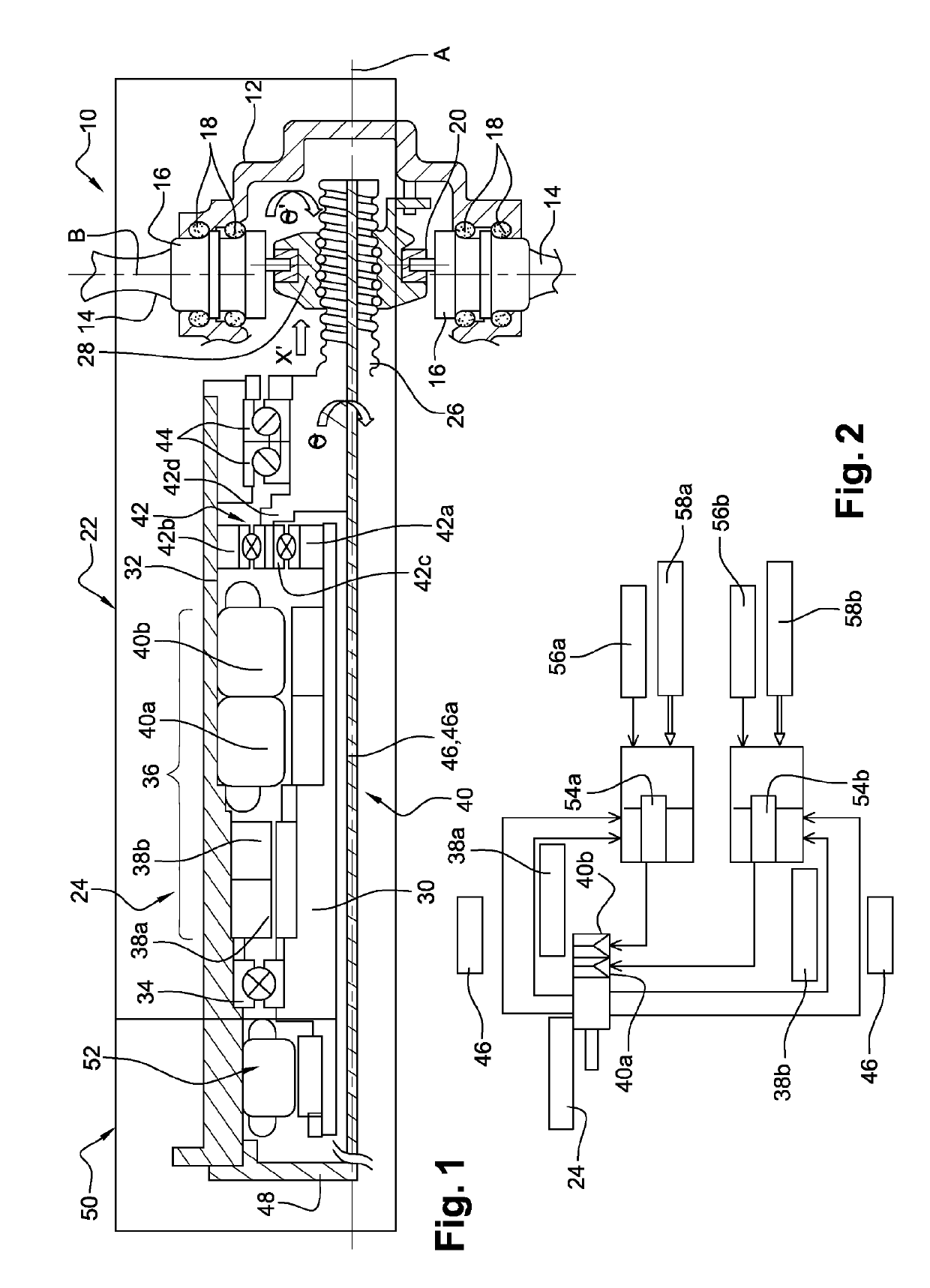
[0054]Reference is first made to FIG. 1.

[0055]A turbomachine propeller 10, and in particular of a turbo prop is in general not streamlined and comprises a movable hub 12 (arrow 8 of FIG. 1) with an axis A of rotation, the hub carrying blades 14 that extend substantially radially with respect to the axis A. Each blade 14 is connected at its radially internal end to a substantially cylindrical plate 16 for supporting and guiding in rotation of the blade for the purpose of setting it in rotation about an axis B, here substantially radial. The plate 16 of each blade 14 is mounted in a housing of the hub 12 and is centred and guided in this housing by bearings 18 extending about the axis B. The radially internal end of each blade comprises an eccentric 20. The latter is integrally connected to the plate 16 and an actuation system 22 can displace it in rotation about the axis B. The displacement of the eccentrics 20 causes a displacement in rotation of the plates 16 and therefore of the b...


PUM


Abstract

A pitch actuation system for a turbomachine propeller, comprising an actuator with a movable portion configured to be connected to blades of the propeller in order to rotate them relative to the blade-pitch setting axes, wherein the actuator is an electromechanical actuator and comprises: blade-pitch control having a transmission screw rotated about an axis; a nut through which said transmission screw passes; and a member configured to engage with the blades in order to move the blades, wherein the nut is connected to the member via a decoupler configured such that a translational movement of the nut causes a translational movement of the member, but rotational movement of the member does not cause rotational movement of the nut.

Description

TECHNICAL FIELD[0001]This invention relates to a pitch actuation system for a turbomachine propeller, such as a turbo prop.STATE OF THE ART[0002]The state of the art comprises especially document U.S. Pat. No. 4,591,313.[0003]A turbo prop comprises at least one propeller comprising a hub and blades carried by the hub and extending substantially radially outwards with respect to the hub and to the axis of rotation of the propeller.[0004]The turbo prop is in general equipped with an actuation system of the propeller pitch, also called an angular setting system of the blades of the propeller. The regulating of the setting of the propeller blades makes it possible to improve their effectiveness by guaranteeing a rotation speed of the propeller for each flight phase.[0005]Each blade can be displaced in rotation about an axis, in general radial, between a first backup position referred to as the feathered position wherein it extends substantially parallel to the axis of rotation of the pr...

Claims


Application Information

Patent Timeline
IPC IPC(8): B64C11/44F02C6/20F01D7/02
CPCB64C11/44F02C6/20F01D7/02F05D2260/74F05D2260/75F05D2260/79F05D2270/62F05D2220/36F01D7/00F02C6/206F02K3/072F05D2220/324F05D2260/40311F05D2270/09
Inventor DE WERGIFOSSE, HUGUETTE
Owner SN DETUDE & DE CONSTR DE MOTEURS DAVIATION S N E C M A
Why Eureka
Try Eureka