
Ultrasonic doppler motion sensor device

a motion sensor and ultrasonic technology, applied in the direction of measurement devices, acoustic wave reradiation, using reradiation, etc., can solve the problems of unknown technology, complete failure of generic sensor technology, and type of known technology, so as to improve noise immunity of inventive devices, reduce undesired pressure fluctuations in ambient air, and effectively reduce the effect of ambient air undesired pressure fluctuations

Active Publication Date: 2019-05-02
STEINEL
View PDF4 Cites 1 Cited by
  • Summary
  • Abstract
  • Description
  • Claims
  • Application Information

AI Technical Summary

Benefits of technology

The present invention is an ultrasound Doppler motion sensor assembly that aims to optimize detection quality and maximize the detection space. It addresses issues such as unwanted feedback, interference from adjacent sensors, and detrimental effects of fluctuations in air pressure. The invention provides a phase shift that can be easily implemented and a stabilization or oscillator frequency that can be adjusted for each individual sensor. Additionally, the invention includes a mixer that can filter out beat frequencies caused by the overlapping of adjacent sensors. These features improve the noise immunity and insensitivity of the motion sensor assembly, making it more robust against interference and fluctuations in the ambient air.

Problems solved by technology

However, this type of known technology also has its problems during everyday operations.
A too strong feedback has a negative impact on a (maximum) motion sensor range, and can even lead to a complete failure of the generic sensor technology.
Another disadvantage to the known technology, in particular when using a plurality of generic ultrasound Doppler motion devices in a shared room or in the area of respective (adjacent) sensors, has to do with undesired influences on the respective adjacent devices, up to and including erroneous detections and erroneous activations.
The cause of this problem lies in the fact that, given (usually quartz-controlled) ultrasound oscillators, the signals of adjacently provided or mounted sensor assemblies are so close to each other in the frequency range that a reception part of a first unit can misinterpret a transmission signal of a second unit as a motion detector signal.
Finally, a general problem (and one that also leads to erroneous activations in the present context of motion sensors) is that pressure fluctuations in the ambient air cannot always be avoided, and likewise cause disturbances.

Method used


Image

  • Ultrasonic doppler motion sensor device
  • Ultrasonic doppler motion sensor device

Examples


Embodiment Construction

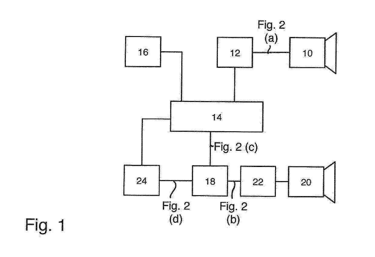
[0017]The device shown on FIG. 1 in a schematic block diagram in a first exemplary embodiment comprises a conventional ultrasound generator (ultrasound transmitter) 10 on the transmitter side, which is exposed to a sinusoidal, continuous signal (CW) by a driver unit 12, with a typical transmission frequency measuring 40 kHz. The transmission signal is kept constant on the driver side in terms of a phase locked loop (PLL) realized there.

[0018]Connected upstream from the driver unit is a central control and filter unit 14, which receives a stabilization signal obtained from a quartz oscillator unit 16, and also relays it to the driver unit 12. As a consequence, the signal of the oscillator unit (stabilization unit) 16 is also used to generate a 40 kHz pulse signal within the framework of the assembly 14 realized by means of a microprocessor unit.

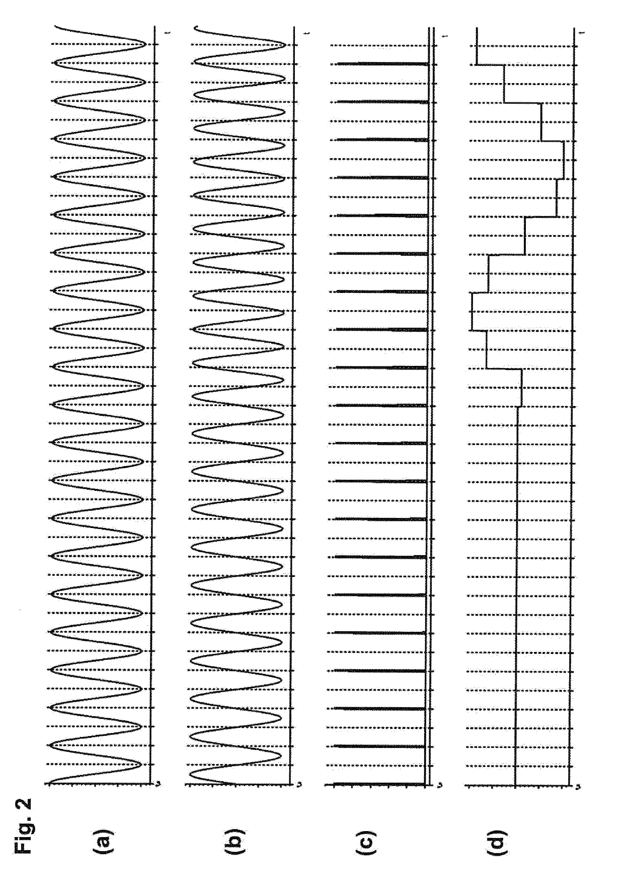
[0019]This pulse signal, once again also phase shifted in the unit 14 in relation to a phase of the transmission signal 14 by digital means, ...


PUM


Abstract

An ultrasonic doppler motion sensor device comprising transmitter means (10, 12) for emitting a continuous ultrasonic transmission signal in a detection space, ultrasonic receiver means (20, 22) for detecting the ultrasonic transmission signal reflected by the detection object as a receive signal, and mixer and detector means (14, 18) for mixing the ultrasonic transmission signal or a signal derived therefrom with the receive signal and / or for demodulating the receive signal and for generating a motion detection signal therefrom, wherein the mixer and detector means are assigned means (14) for the adjustable generation of a phase shift greater than 0° between a phase of the ultrasonic transmission signal and a periodic impulse signal at the mixer or detector means for scanning and mixing the receive signal.

Description

BACKGROUND OF THE INVENTION[0001]The present invention relates to an ultrasound Doppler motion sensor assembly according to the preamble of the main claim. The invention further relates to the use of such a motion sensor device.[0002]Generally known from prior art are ultrasound Doppler motion sensor devices according to the preamble of the main claim. The latter are usually used in an interior space, in particular for purposes of controlling illumination in response to the detected motion, wherein a continuous transmission signal having a typical carrier frequency of approx. 40 kHz radiated (emitted) by the transmitting means is reflected by an object moving in the detection space, the reflected signal is received by the ultrasound reception means, after which mixer and detector means are used to determine a Doppler frequency that depends on a speed of motion of the detection object within the framework of demodulating the reception signal, and evaluate it for the desired motion de...

Claims


Application Information

Patent Timeline
Patent Type & Authority Applications(United States)
IPC IPC(8): G01S15/52G01S7/534
CPCG01S15/523G01S7/534
Inventor JAKOBS, DIRKTHIELE, MARCEL
Owner STEINEL
Learn More