Plasma processing apparatus

Inactive Publication Date: 2019-05-02
TOKYO ELECTRON LTD
View PDF0 Cites 1 Cited by
  • Summary
  • Abstract
  • Description
  • Claims
  • Application Information

AI Technical Summary

Benefits of technology

[0016]As described above, maintenance of components

Problems solved by technology

Therefore, it is not easy to maintain p

Method used


Image

  • Plasma processing apparatus
  • Plasma processing apparatus
  • Plasma processing apparatus

Examples


Example

[0028]Hereinafter, various embodiments will be described in detail with reference to the drawings. In respective drawings, the same or corresponding portions will be denoted by the same reference numerals.

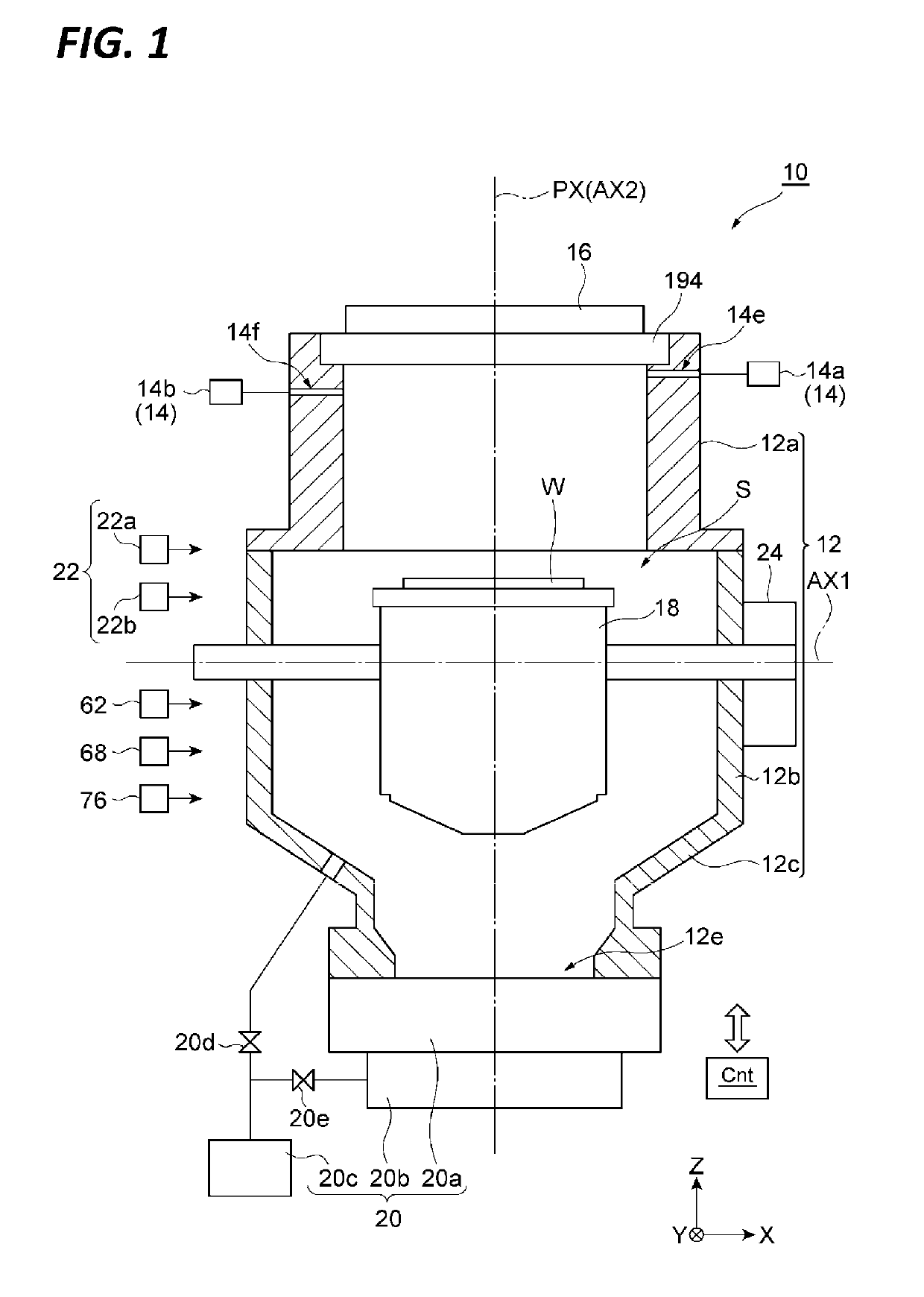
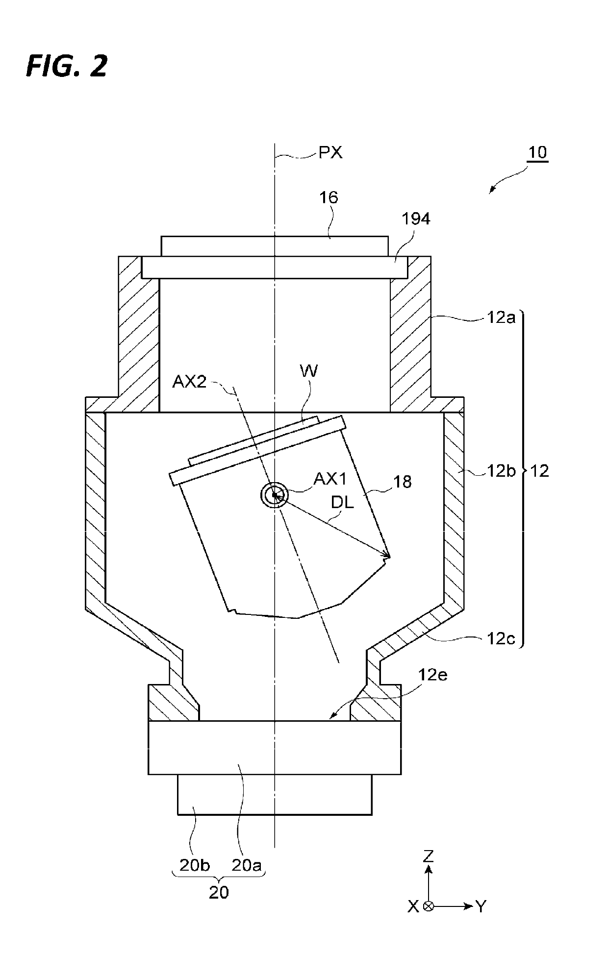
[0029]FIGS. 1 and 2 are views schematically illustrating a plasma processing apparatus according to an embodiment, in which the plasma processing apparatus is illustrated by cutting a chamber body in a plane including an axis PX extending in the vertical direction. In FIG. 1, the plasma processing apparatus is illustrated in the state where a rotational direction position around a first axis AX1 of a support structure is set such that a second axis AX2 described later coincides with the axis PX (a non-tilted state). In FIG. 2, the plasma processing apparatus is illustrated in the state where a rotational direction position around the first axis AX1 of the support structure is set such that the second axis AX2 intersects the axis PX (a tilted state).

[0030]The plasma processing appar...


PUM

PropertyMeasurementUnit
Widthaaaaaaaaaa

Abstract

A plasma processing apparatus includes a chamber body that provides a chamber, a support structure which supports a workpiece inside the chamber body, and a first drive device which rotates the support structure inside the chamber body about a first axis that extends in a direction orthogonal to the vertical direction. The support structure includes a holding unit including an electrostatic chuck which holds the workpiece and which is rotatable around a second axis orthogonal to the first axis, a container provided below the holding unit, and a second drive device which rotates the holding unit around the second axis. The container has a cylindrical container body and a bottom cover configured to close a bottom side opening in the container body. The bottom cover is detachable from the container body.

Description

TECHNICAL FIELD[0001]Exemplary embodiments of the present disclosure relate to a plasma processing apparatus.BACKGROUND[0002]In manufacturing an electronic device such as, for example, a semiconductor device, a plasma processing (e.g., a plasma etching) may be performed on a workpiece. The plasma processing is performed using a plasma processing apparatus. In plasma processing apparatus, a gas is supplied into a chamber provided by a chamber body, and the gas is excited by a plasma source. Thus, plasma is generated in the chamber, and the workpiece supported by a sample table is processed by ions and / or radicals in the plasma.[0003]As one type of such a plasma processing apparatus, there is a type having a rotation drive device that rotates the sample table about a plasma lead-out direction as an axis and a tilt drive device that tilts the sample table with respect to the plasma lead-out direction. Such a plasma processing apparatus is disclosed in Patent Document 1. In the plasma p...

Claims


Application Information

Patent Timeline
IPC IPC(8): H01L21/683H01J37/32C23C16/44
CPCH01L21/6831H01J37/32477C23C16/4401H01L21/67109H01L21/68742H01L21/68764H01L21/68785H01L21/68792H01L21/3065H01L21/67069H05H1/46
Inventor MATSUMOTO, KAZUYAHOSAKA, YUKIOHATA, MITSUNORIYAMAMOTO, TAKASHI
Owner TOKYO ELECTRON LTD
Why Eureka
Try Eureka