Charging Control System and Power Charging Management Method Thereof

a control system and power charging technology, applied in the field of control system, can solve the problems of circuit breaker tripping and the reduction of the lifetime of the circuit breaker, and achieve the effect of improving the quality of charging and safety

Active Publication Date: 2019-05-02
AVER INFORMATION INC
View PDF0 Cites 0 Cited by
  • Summary
  • Abstract
  • Description
  • Claims
  • Application Information

AI Technical Summary

Benefits of technology

[0008]The purpose of the present invention is to provide a charging control system and a power charging management method thereof, which can enhance quality of charging and safety as a whole by managing and distributing charging power.

Problems solved by technology
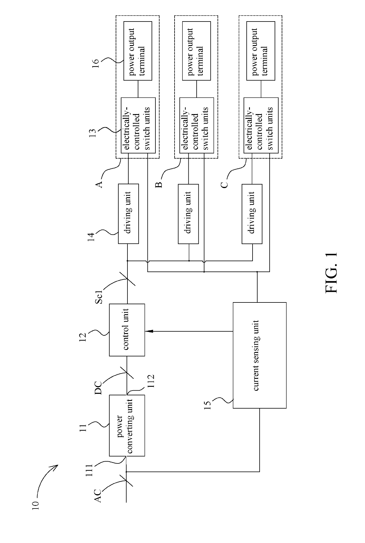
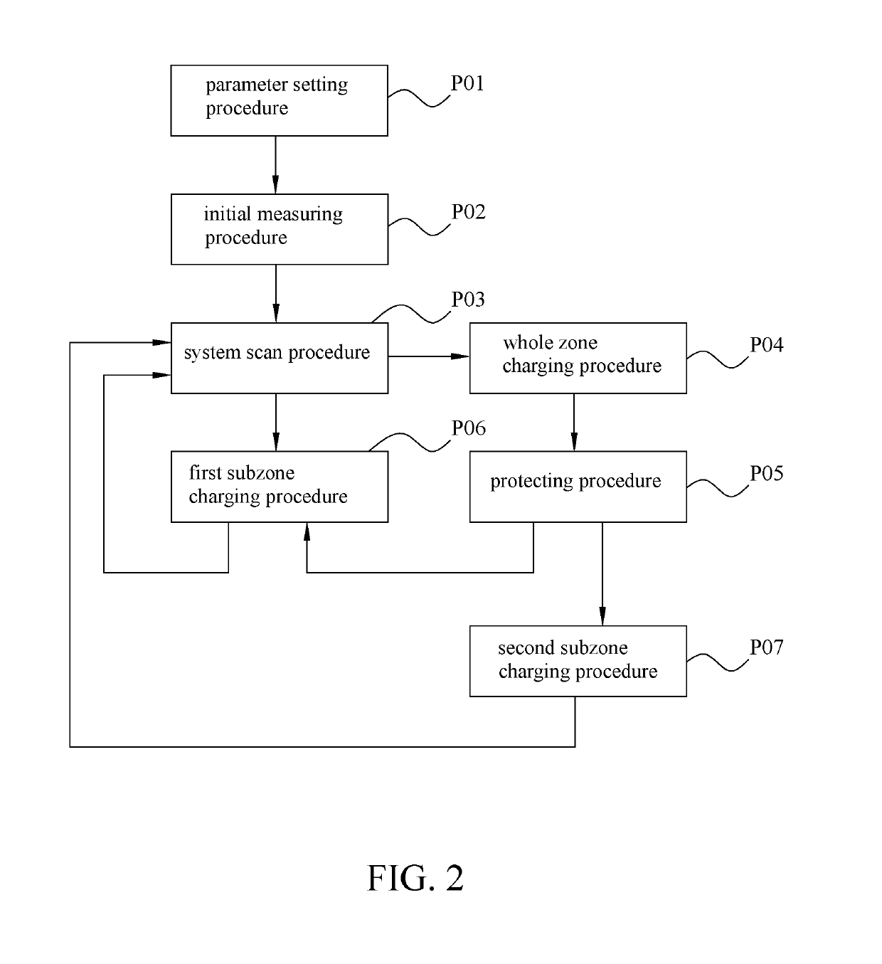
However, according to various amounts of remained power level of the digital devices, various amounts of current values are required for the charging operation.
As a result, in case that the charging control system is required to simultaneously charge tens of digital devices, the required current value may exceed a upper limited level of a power distribution system that is coupled to the charging control system, and thus causes tripping of the circuit breaker.
However, the electrically-controlled switch will be frequently switched and lifetime thereof will thus be decreased.

Method used


Image

  • Charging Control System and Power Charging Management Method Thereof
  • Charging Control System and Power Charging Management Method Thereof
  • Charging Control System and Power Charging Management Method Thereof

Examples


first embodiment

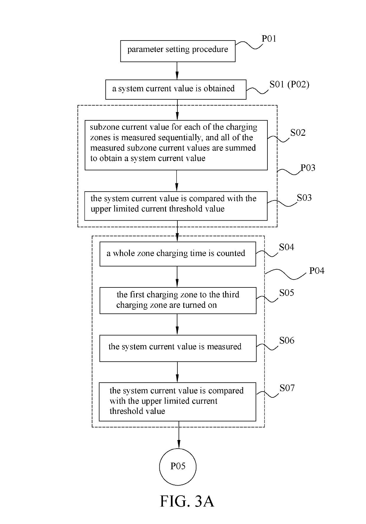
[0071]For the power charging management method of the present invention, parameters of the charging system are set as the following: the predetermined scan charging time is set as 10 sec, the predetermined charging zone number is set as 3, the predetermined subzone charging time is set as 20 minutes, the predetermined lower limited current charging time is set as 3 minutes, the predetermined whole zone charging time is set as 20 minutes, the upper limited current threshold value is set as 10A, and the lower limited current threshold value is set as 1A.

[0072]After execution of the system scan procedure at steps S23 to S25, required current values for each charging zone are shown in table T1:

TABLE T1charging zonecurrent (A)The first charging zone7The second charging zone3The third charging zone7

[0073]From Table T1, sum of subzone currents of each charging zone is represented as: current of the first charging zone+current of the second charging zone+current of the third charging zone=1...

second embodiment

[0079]For the power charging management method of the present invention, parameters of the charging system are set as the following: the predetermined scan charging time is set as 10 sec, the predetermined charging zone number is set as 3, the predetermined subzone charging time is set as 20 minutes, the predetermined lower limited current charging time is set as 3 minutes, the predetermined whole zone charging time is set as 20 minutes, the upper limited current threshold value is set as 10A, and the lower limited current threshold value is set as 1A.

[0080]After execution of the system scan procedures at steps S23 to S25, required current value for each charging zone are shown in table T4:

TABLE T4charging zonecurrent (A)The first charging zone2The second charging zone0.5The third charging zone2

[0081]From Table T4, sum of subzone currents of each charging zone is represented as: current of the first charging zone+current of the second charging zone+current of the third charging zone...


PUM


Abstract

A power charging management method is cooperated with a charging control system. The charging control system includes a control unit and a plurality of charging zones. The control unit controls the charging zones to turn on or turn off so as to selectively allow a charging power to be provided to the charging zones. The power charging management method includes a system scan procedure, a whole zone charging procedure, a protecting procedure and a subzone charging procedure.

Description

CROSS REFERENCE TO RELATED APPLICATIONS[0001]This Non-provisional application claims priority under 35 U.S.C. § 119(a) on patent application Ser. No. 10 / 6136448 filed in Taiwan on Oct. 24, 2017, the entire contents of which are hereby incorporated by reference.BACKGROUND1. Technical Field[0002]The present invention relates to a control system, in particular, to a charging control system and a power charging management method thereof.2. Description of Related Art[0003]As technology grows rapidly in recent years and concerning environmental protection, digital devices such as tablets or laptops are introduced for the academic institutions to perform education, so that a purpose of paperless-ness may be achieved.[0004]In order to simultaneously adopt and charge several to tens of digital devices, a charging control system is also introduced for the academic institutions to achieve the above goals. The charging control system is usually designed to be capable of adopting tens of digital...

Claims


Application Information

Patent Timeline
Patent Type & Authority Applications(United States)
IPC IPC(8): H02J7/00
CPCH02J7/0022H02J7/0024H02J7/0026H02J7/0083H02J7/00304H02J2310/14H02J7/0013H02J3/14Y04S20/222Y04S20/242Y02B70/30Y02B70/3225H02J7/00718
Inventor HSU, CHI-FACHANG, CHAO-HUNGCHOU, LIEN-KAIYU, CHENG-CHENGLIN, JY-SHYAN
Owner AVER INFORMATION INC
Why Eureka
Try Eureka