Rotary Electric Machine

a rotary electric machine and concentrated winding technology, applied in the direction of braking system, magnetic circuit rotating parts, shape/form/construction, etc., can solve the problems of high manufacturing cost, high price of motor, high cost of materials such as magnets and coils, etc., and achieve the effect of efficient manufacturing work

Inactive Publication Date: 2019-05-02
HITACHI AUTOMATIVE SYST ENG
View PDF0 Cites 1 Cited by
  • Summary
  • Abstract
  • Description
  • Claims
  • Application Information

AI Technical Summary

Benefits of technology

[0028]According to the invention, a lead wire and a jumper wire to a tooth far away from the adjacent tooth can be disposed at the end of the coil on an axially reverse side, so that the manufacturing work can be efficiently performed on the coil. Objects, configurations, and features other than those described above will become clear through the explanation about the following embodiments.

Problems solved by technology

The price of the motor includes the cost of materials such as magnets and coils and the cost of manufacturing.
In a distributed winding, it is known that the cogging torque and the torque pulsation can be made small, the vibration can be made less by increasing the spatial order of the electromagnetic exciting force, the structure is complicate compared to a concentrated winding, the size in an axial direction is large, and the manufacturing cost is increased.
However, it is known that the electromagnetic exciting force is a second spatial order which causes vibration.
Since the end of the same coil is limited in space, a procedure of the work is complicated and a cost is required for additional members.
Therefore, a manufacturing work of the coils becomes complicated.

Method used


Image

  • Rotary Electric Machine
  • Rotary Electric Machine
  • Rotary Electric Machine

Examples


first embodiment

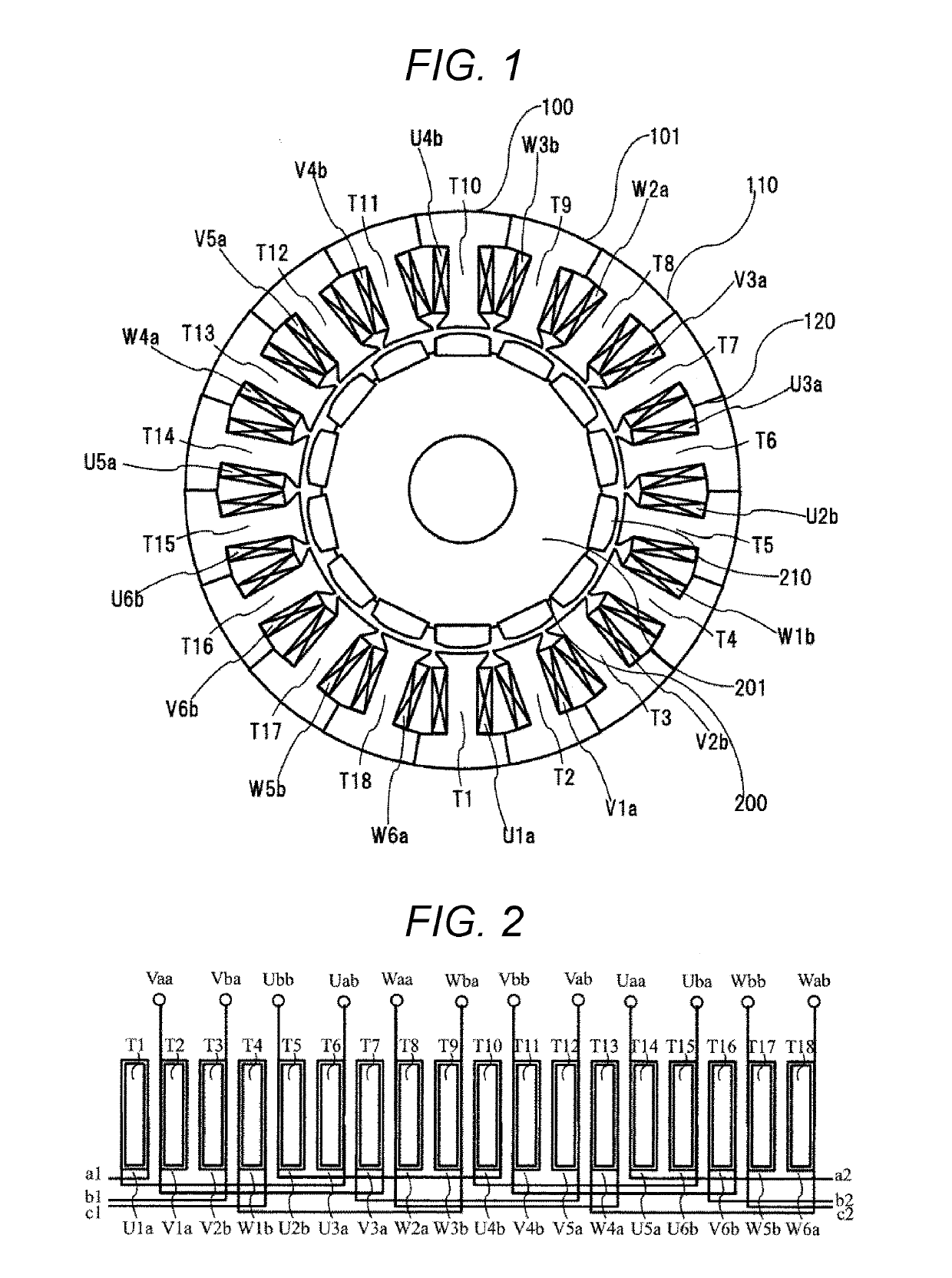
[0051]The description will be given about a configuration of a permanent magnet type brushless motor having 14 poles and 18 slots according to a first embodiment of the invention using FIGS. 1 to 4(D).

[0052]In FIG. 1, U5a, U1a, and U3a are configured as 3-series coils, and similarly V1a, V3a, and V5a and W2a, W4a, and W6a are configured as 3-series coils, so that Type-a 3-series coils are configured. In addition, U2b, U4b, and U6b are configured as 3-series coils, and similarly V4b, V6b, and V2b and W5b, W1b, and W3b are configured as 3-series coils, and these coils are considered as Type-b 3-series coils. In the respective 3-series coils, the numbers of times of winding of the 3-series coils are sequentially set to a half integer Na, an integer N, and a half integer Nb.

[0053]In this case, Group A: the number of times of winding of each of U1a, W1b, V3a, U4b, W4a, and V6b is the integer N, Group B: the number of times of winding of each of V1a, U2b, W2a, V4b, U5a, and W5b is the hal...

second embodiment

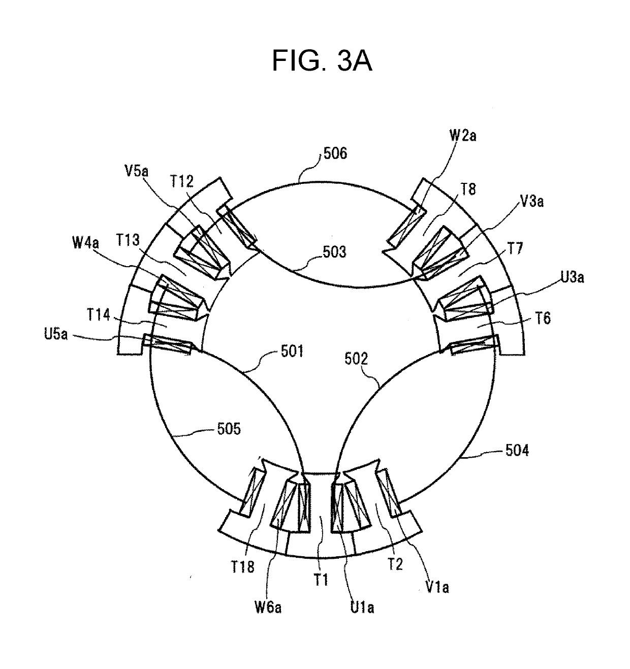
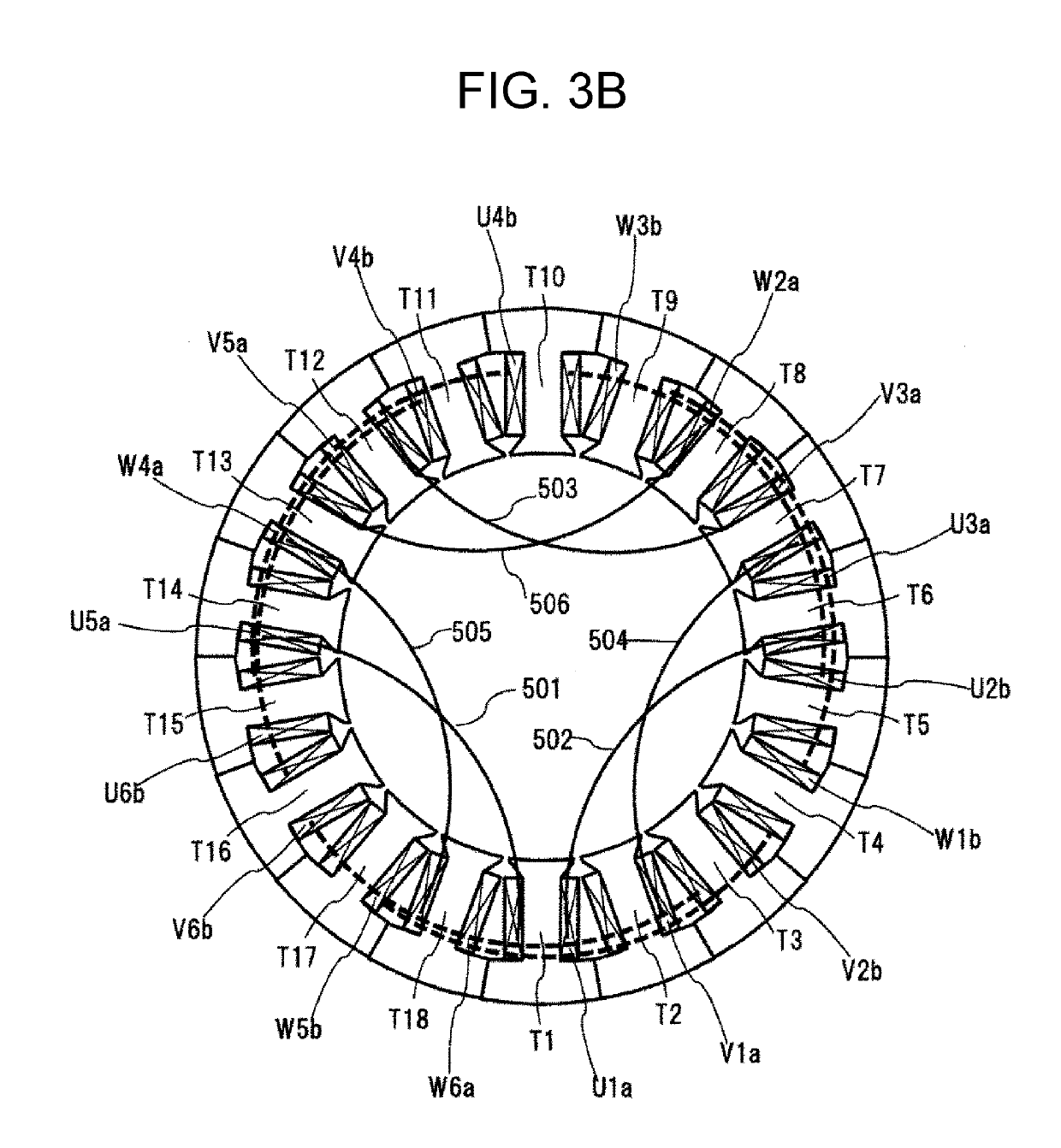
[0077]The configuration of the permanent magnet type brushless motor having 14 poles and 18 slots according to a second embodiment of the invention will be described using FIGS. 5 to 6(D).

[0078]In FIG. 5, U3a, U1a, and U2b are configured as 3-series coils, and similarly V5a, V3a, and V4b and W6a, W4a, and W5b are configured as 3-series coils, and these coils are considered as Type-a 3-series coils. In addition, U6b, U4b, and U5a are configured as 3-series coils, and similarly V2b, V6b, and V1a and W3b, W1b, and W2a are configured as 3-series coils, and these coils are considered as Type-b 3-series coils.

[0079]In the respective 3-series coils, the numbers of times of winding of the 3-series coils are sequentially set to the half integer Na, the integer N, and the half integer Nb. In this case, Group A: the number of times of winding of each of U1a, W1b, V3a, U4b, W4a, and V6b is the integer N, Group B: the number of times of winding of each of V1a, U2b, W2a, V4b, U5a, and W5b is the ...

third embodiment

[0088]The description will be given using FIGS. 7 and 8 about a configuration of the permanent magnet type brushless motor having 14 poles and 18 slots according to a third embodiment of the invention.

[0089]In FIG. 7, U3a, U2b, U1a are configured as 3-series coils, and similarly V5a, V4b, and V3a and W6a, W5b, and W4a are configured as 3-series coils, and these coils are considered as Type-a 3-series coils. In addition, U6b, U5a, and U4b are configured as 3-series coils, and similarly V2b, V1a, and V6b and W3b, W2a, and W1b are configured as 3-series coils, and these coils are considered as Type-b 3-series coils.

[0090]In the respective 3-series coils, the numbers of times of winding of the 3-series coils are sequentially set to the integer N, the half integer Na, and the half integer Nb. In this case, Group A: the number of times of winding of each of U1a, W1b, V3a, U4b, W4a, and V6b is the half integer Nb, Group B: the number of times of winding of each of V1a, U2b, W2a, V4b, U5a, ...


PUM


Abstract

An object of the invention is to provide a concentrated winding brushless motor of a permanent magnet type, in which a lead wire and a jumper wire to a tooth far away from the adjacent tooth are disposed at the ends of coils on an axially reverse side in order to make a manufacturing work of coils efficient. In order to achieve the object, there is provided a brushless motor which is provided with a concentrated winding stator and a permanent magnet type rotor, a stator coil is wound to satisfy that the number of times of winding of coils of a tooth connected to the lead wire is set to a half integer or, in a case where there is a coil which is connected to the coil of the tooth connected to the lead wire, the number of times of winding of the teeth is set to a half integer, the number of times of winding of the coil of the tooth connected to the lead wire or a coil of a tooth far away from the adjacent tooth which are connected by the jumper wire, or the number of times of winding of the coil of the tooth adjacently connected to the coil of the tooth far away from the adjacent tooth which are connected by the jumper wire is set to an integer.

Description

TECHNICAL FIELD[0001]The present invention relates to a permanent magnetic concentrated winding brushless motor and an electric auxiliary system for automobiles such as an electric power steering device using the brushless motor.BACKGROUND ART[0002]As a hydraulic pressure is replaced with electrical motorization and the markets of a hybrid automobile and an electric automobile are widened, a rate of mounting the electric power steering (hereinafter, referred to as EPS) device is steeply increased.[0003]In an EPS device, an electric motor assists the operation of a steering wheel. Therefore, a driver can feel torque pulsation of the motor through the steering wheel. Therefore, in an EPS motor, there is a need to set a cogging torque to about 1 / 1000 of an assist torque of the motor, and to set the torque pulsation to about 1% of the assist torque.[0004]Further, in recent years, an improvement in pleasant driving and noise reduction in the interior of the vehicle are progressing agains...

Claims


Application Information

Patent Timeline
Patent Type & Authority Applications(United States)
IPC IPC(8): H02K3/28H02K1/14H02K1/27H02K3/52H02K21/16
CPCH02K3/28H02K1/146H02K1/278H02K3/522H02K21/16H02K2203/06H02K29/03B62D5/0403B60T13/74H02K3/18H02K15/04
Inventor TAGO, KAZUTAMIKANAZAWA, HIROSHIKITAMURA, HIDEKINAKAYAMA, KENJI
Owner HITACHI AUTOMATIVE SYST ENG
Why Eureka
Try Eureka