Automated milking system safety valve arrangement

a technology of automatic milking system and safety valve, which is applied in the direction of couplings, pipe couplings, mechanical equipment, etc., can solve the problems of difficulty in providing adequate protection of milk lines, difficulty in providing adequate milk line protections, and possible less effective dips, so as to achieve the effect of improving and timely maintenan

Active Publication Date: 2019-05-09
GEA FARM TECH
View PDF0 Cites 12 Cited by
  • Summary
  • Abstract
  • Description
  • Claims
  • Application Information

AI Technical Summary

Benefits of technology

[0015]A valve assembly in accordance with the present invention includes: a conduit defining a flow path having a first end and a second end; a first valve having an open position and a closed position to close the first end of the flow path; a second valve having an open position and a closed position to close the second end of the flow path; a pressurized fluid source in fluid communication with the flow path when the first valve is closed and the second valve is closed; and a pressure monitor in communication with the flow path to d...

Problems solved by technology

Milk line protection systems can be complicated because pre-dipping and post-dipping require that teat dipping fluids be delivered in precise dosages and in a timely fashion to provide proper teat treatment, system cleaning, system timing, and milk line protection.
Given the short time durations in which teat dip must pass through the teat dip fluid manifold, providing adequate milk line protections can be challenging.
For example, water should not be allowed to contaminate teat dip before it is delivered to a teat because the dip can be diluted and possibly less effective.
Conversely, teat dip should not be allowed to contaminate water and air lines, which could foul the system and require additional maintenance.
Nonetheless, teat dips and/or backflushing fluids can have an adverse effect...

Method used


Image

  • Automated milking system safety valve arrangement
  • Automated milking system safety valve arrangement
  • Automated milking system safety valve arrangement

Examples


first embodiment

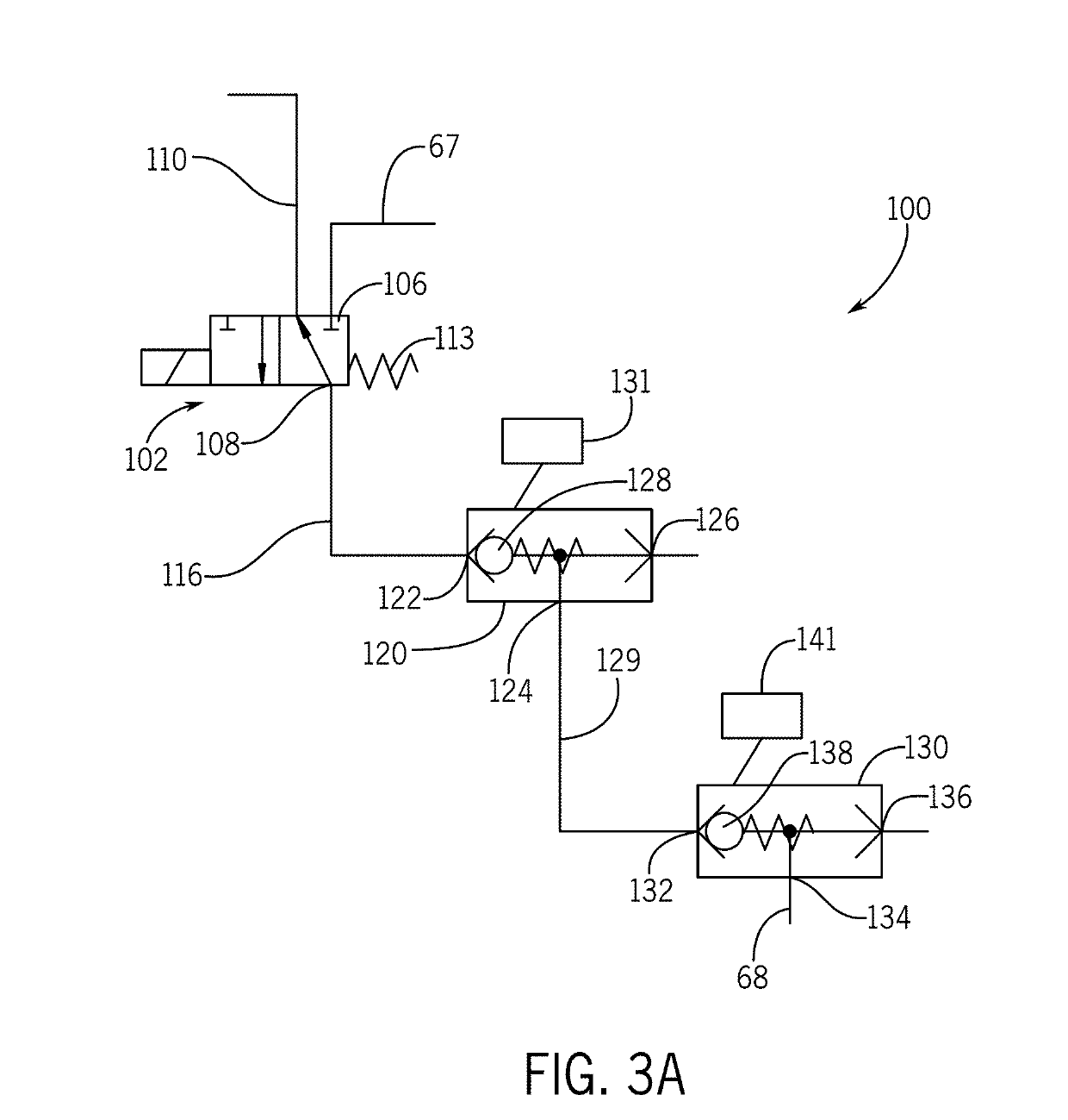
[0068]FIGS. 3A through 3F depict a safety valve 100 in accordance with the present invention. FIG. 3A uses different valve schematics than FIGS. 3B through 3F to aid in understanding the invention. The safety valve 100 is actually a combination of valves having an upstream valve 102 that is preferably a 2 postion-3 way valve having an inlet 106, an outlet 108, and vent 110. The inlet 106 is in fluid communication with a delivery line 67 from the manifold 50 or 52. The outlet 108 feeds a first conduit 116.

[0069]In between the inlet 106 and the outlet 108, is the vent 110, which together form a “block-bleed-block” arrangement to protect downstream milk lines from upstream teat dip fluids. The 2 positon-3 way style valve is desirable, because it preferably uses valve seats on which valve heads bear when in the closed position, as opposed to seals in a spool valve which must slide and can be subject to swelling and seizure after extended exposure to teat dip. Nonetheless, under appropri...

second embodiment

[0083]FIG. 4 illustrates a safety valve 200 in accordance with the present invention, which includes an upstream valve 204, a galley 206, a downstream valve 208, a pneumatic pressure valve 212 in communication with the galley 206, and a pressure monitor 216 also in fluid communication with the galley 206. A vent check valve 214 is also provided to ventilate the galley 206 before or simultaneously with teat dip flowing into the safety valve galley 206, so that the dip pressure does not have to be greater than the galley pressure. In place of the vent 214, or in addition thereto, a vacuum can be applied to the galley 206 to evacuate any pressure and to draw fluid into and through the safety valve 200.

[0084]The upstream valve 204, the downstream valve 208, and the pneumatic pressure valve 212 are preferably all normally closed, 2 positon-2 way valves, which are relatively inexpensive to maintain and avoid the use of spools and related seals that can swell and even seize up after prolon...

third embodiment

[0091]FIG. 5 illustrates a safety valve 300 in accordance with the present invention. This safety valve 300 includes an upstream valve 304, a galley 306, a downstream valve 308, a pneumatic pressure valve 312, and a pressure monitor 316, as generally arranged in other embodiments described herein. The galley 306 and all of the galleys of the present invention can be any shape or length, including having tapers and branches that lead to the various valves, but is preferably generally tubular in shape for efficient fluid flow.

[0092]In this embodiment the upstream valve 304 is a solenoid-operated 2 way-2 position valve, with an inlet 320 and an outlet 322. The downstream valve 308 is illustrated as a 2 position-3 way valve with an inlet 324 that is normally closed to the galley 306, and an outlet 326 that is normally open to a vent 328 to atmosphere. The pneumatic pressure valve 312 is as described above for other embodiments and receives pressurized gas, such as air, from a source lin...


PUM


Abstract

A safety valve arrangement and method, having an upstream block valve, a downstream block valve, and a pressure monitored galley between the upstream valve and the downstream valve.

Description

CROSS REFERENCE TO RELATED APPLICATION[0001]This application claims the benefit of U.S. Provisional Application 62 / 581,514, filed Nov. 3, 2017, and U.S. Provisional Application 62 / 581,526, filed Nov. 3, 2017, the disclosures of which are incorporated by reference herein.FIELD AND BACKGROUND OF THE INVENTION[0002]The present invention relates generally to safety valves for segregating dairy milk lines from contamination by other fluids such as teat dips, and more particularly to safety valves with improved safety and monitoring features.[0003]Dairy milking systems as they relate to the present invention include a cluster of teat cups, each of which is matched with a flexible teat cup liner that is attached to a teat of a dairy animal with a vacuum. Vacuum is applied in pulses between the shell and liner to facilitate movement of the flexible liner to milk the dairy animals. Milk flows from the dairy animal through each flexible liner and then through a milk tube to a milker unit coll...

Claims


Application Information

Patent Timeline
IPC IPC(8): A01J5/007A01J7/02A01J7/04F16L55/07
CPCA01J5/007A01J7/022A01J7/04F16L55/07F16L2201/20F16L2201/30A01J5/044A61K9/0041
Inventor STUESSEL, MATTHEW JSCHULZE-WILMERT, WOLFGANGORBAN, THOMAS
Owner GEA FARM TECH
Why Eureka
Try Eureka