Image processing apparatus, image processing method, and program

Inactive Publication Date: 2019-05-09
DENSO CORP
View PDF6 Cites 0 Cited by
  • Summary
  • Abstract
  • Description
  • Claims
  • Application Information

AI Technical Summary

Benefits of technology

[0011]According to the image processing method in the other aspect of the present disclosure, it is possible to determine easily whethe

Problems solved by technology

When the images acquired by the in-vehicle camera include an area lower in luminance than the surroundings

Method used


Image

  • Image processing apparatus, image processing method, and program
  • Image processing apparatus, image processing method, and program
  • Image processing apparatus, image processing method, and program

Examples


Example

First Embodiment

[0028]1. Configuration of an Image Processing Apparatus 1

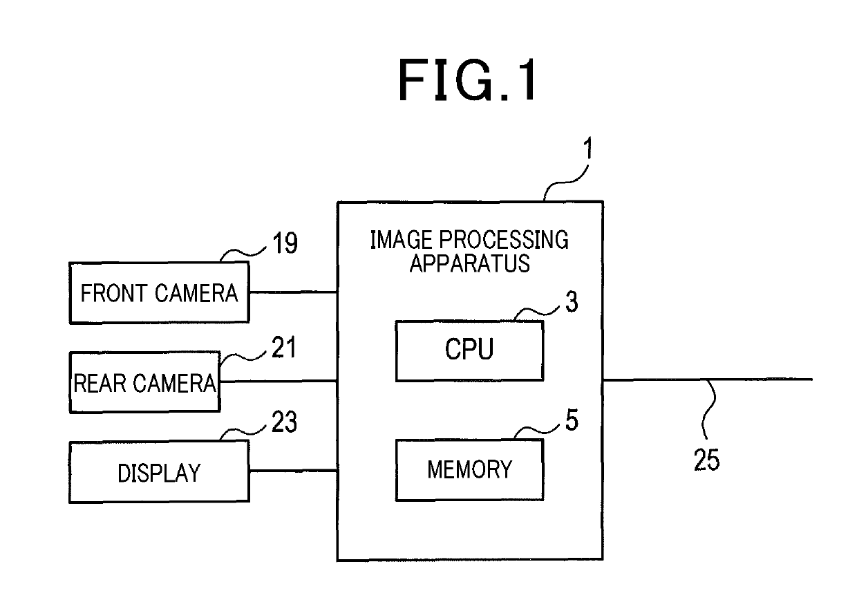
[0029]A configuration of an image processing apparatus 1 will be described with reference to FIGS. 1 to 3. The image processing apparatus 1 is an in-vehicle apparatus installed in a vehicle. The vehicle equipped with the image processing apparatus 1 will be hereinafter referred to as a subject vehicle. The image processing apparatus 1 is mainly formed of a known microcomputer having a CPU 3 and a semiconductor memory such as a RAM, a ROM, or a flash memory (hereinafter, referred to as a memory 5). Various functions of the image processing apparatus 1 are implemented by the CPU 3 executing programs stored in a non-transitory tangible recording medium. In this example, the memory 5 is equivalent to the non-transitory tangible recording medium storing the programs. When any of the programs is executed, a method corresponding to the program is executed. The image processing apparatus 1 may be formed from one or mor...

Example

Second Embodiment

[0075]1. Differences from the First Embodiment

[0076]A second embodiment is basically similar in configuration to the first embodiment. Accordingly, the same components will not be described but the differences will be mainly described. The same reference signs as those in the first embodiment represent the same components as those in the first embodiment, and thus the foregoing descriptions will be referred to here.

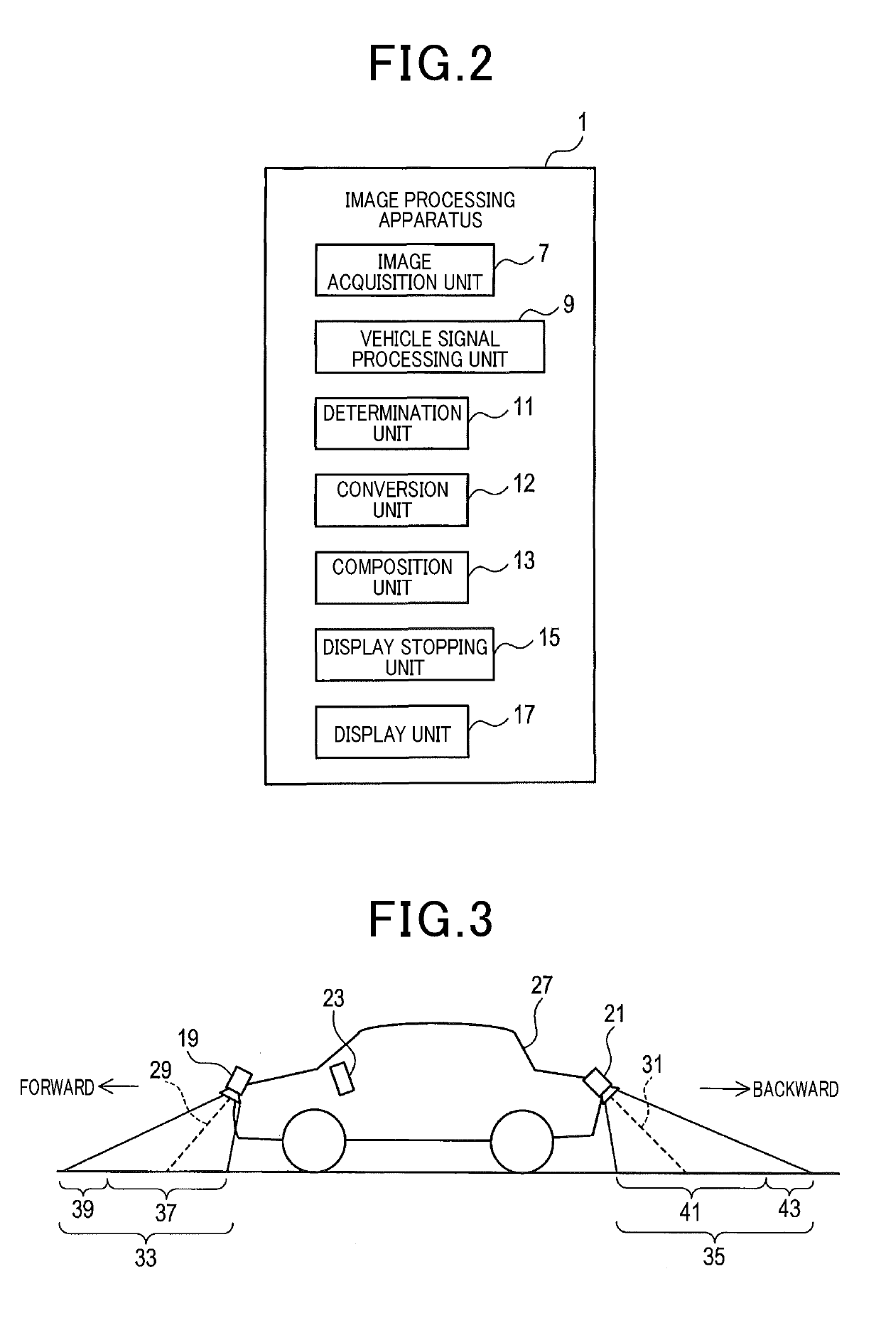
[0077]The subject vehicle includes a right camera 57 and a left camera 59 as illustrated in FIG. 8. The right camera 57 acquires a scenery on the right side of the subject vehicle to generate an image. The left camera 59 acquires a scenery on the left side of the subject vehicle to generate an image.

[0078]An image processing apparatus 1 includes an image acquisition unit 7, a vehicle signal processing unit 9, a determination unit 11, a conversion unit 12, a composition unit 13, a recognition unit 13, a recognition unit 56, and a recognition stopping unit ...

Example

Third Embodiment

[0102]1. Differences from the Second Embodiment

[0103]A third embodiment is basically similar in configuration to the second embodiment. The same components will not be described but the differences will be mainly described here. The same reference signs as those in the second embodiment represent identical components and thus the foregoing descriptions will be referred to here.

[0104]An image processing apparatus 1 includes an image acquisition unit 7, a vehicle signal processing unit 9, a determination unit 11, a conversion unit 12, a composition unit 13, a recognition unit 56, and a change condition unit 73 as illustrated in FIG. 13, as functional components implemented by the CPU 3 executing programs.

[0105]2. Process Performed by the Image Processing Apparatus 1

[0106]The process performed by the image processing apparatus 1 will be described with reference to FIG. 14. Steps 41 to 51 described in FIG. 14 are similar to steps 21 to 31 in the second embodiment.

[0107]I...


PUM


Abstract

An image processing apparatus includes an image acquisition unit and a determination unit. The image acquisition unit uses a camera to acquire a first image representing an area in a first relative position and a second image representing an area in a second relative position closer to the moving direction of the vehicle than the first relative position. The determination unit compares the first image with the second image acquired earlier than the first image and representing an area overlapping the first image for luminance and/or the intensity of a predetermined color component to determine whether there exists a specific area higher in luminance than the surroundings or lower in luminance than the surroundings in the first image.

Description

CROSS-REFERENCE TO RELATED APPLICATION[0001]This international patent application is to claim priority based on Japanese Patent Application No. 2016-088203, filed on Apr. 26, 2016, in the Japan Patent Office, and the entire disclosure of Japanese Patent Application No. 2016-088203 is hereby incorporated by reference.TECHNICAL FIELD[0002]The present disclosure relates to an image processing apparatus, an image processing method, and a program.BACKGROUND ART[0003]There have been known techniques for acquiring images of areas around a vehicle by an in-vehicle camera and performing various processes using the images. For example, there is known a technique for recognizing lane markers from the acquired images.[0004]Further, there is also known image processing as described below. First, an in-vehicle camera is used to acquire a plurality of images of areas around the vehicle at different times. Then, the plurality of images are converted into bird's-eye view images, and the plurality of...

Claims


Application Information

Patent Timeline
IPC IPC(8): G06K9/46H04N5/265H04N5/262G06K9/00G06K9/03G06V10/60
CPCG06K9/4661H04N5/265H04N5/2628G06K9/00798G06K9/036H04N5/247H04N7/181G08G1/167G08G1/168B60R2300/607G06T3/4038G06T2207/30256G06T5/50G06T5/008G06V20/588G06V10/60H04N23/63H04N23/90G06T7/60G06T7/00
Inventor SHIMIZU, SHUICHISHIGEMURA, SHUSAKU
Owner DENSO CORP
Why Eureka
Try Eureka