LED Light Engine

a technology of led light and engine, which is applied in the direction of instruments, lighting and heating apparatus, printed circuit non-printed electric components association, etc., can solve the problems of trace cracking and solder cracking, difficult to obtain uniform illumination, and screw load on the module, so as to improve the uv resistance and operability, improve the bonding, and reduce the likelihood of moisture leakage

Inactive Publication Date: 2019-05-16
GENERAL LED OPCO LLC
View PDF5 Cites 3 Cited by
  • Summary
  • Abstract
  • Description
  • Claims
  • Application Information

AI Technical Summary

Benefits of technology

[0010]After the printed circuit board is placed between the top enclosure and the bottom enclosure, the combination of the top enclosure, the printed circuit board, and the bottom enclosure are placed in a mold used in a molding machine. A molten sealant material is then injected onto the combination of the top enclosure, the printed circuit board, and the bottom enclosure. Once cooled, the molten plastic sealant material forms strain reliefs around, and covers the insulated wires positioned on the bottom of the printed circuit board. The molten sealant materi...

Problems solved by technology

However, in irregularly shaped signage, the irregular shape of the sign makes it difficult to obtain uniform illumination.
However, there are problems with the effects of the screw load on the modules.
The screw load is imparted on the printed circuit boards which can cause trace cracking and solder cracking.
This can create leaking issues and, i...

Method used


Image

  • LED Light Engine
  • LED Light Engine
  • LED Light Engine

Examples


Embodiment Construction

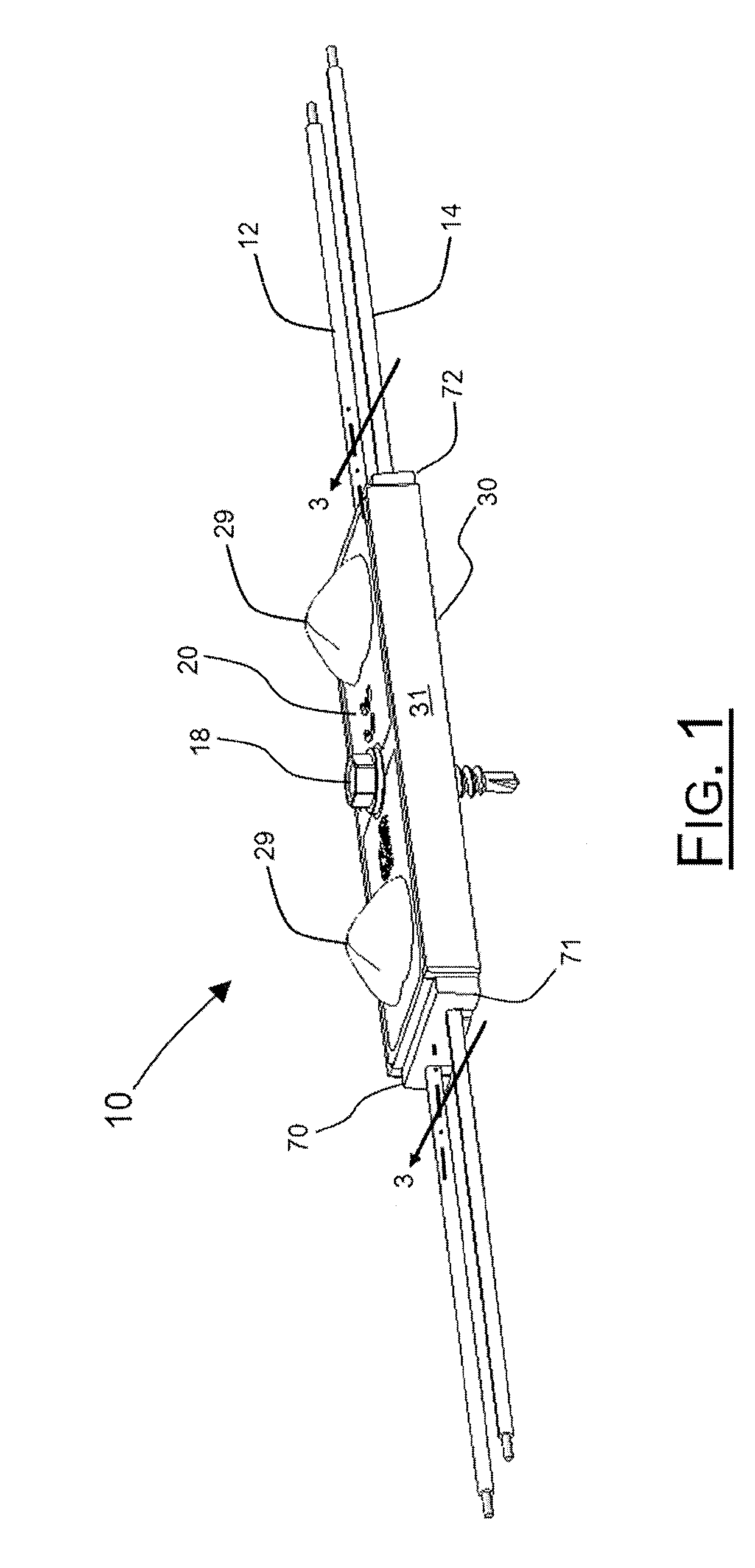
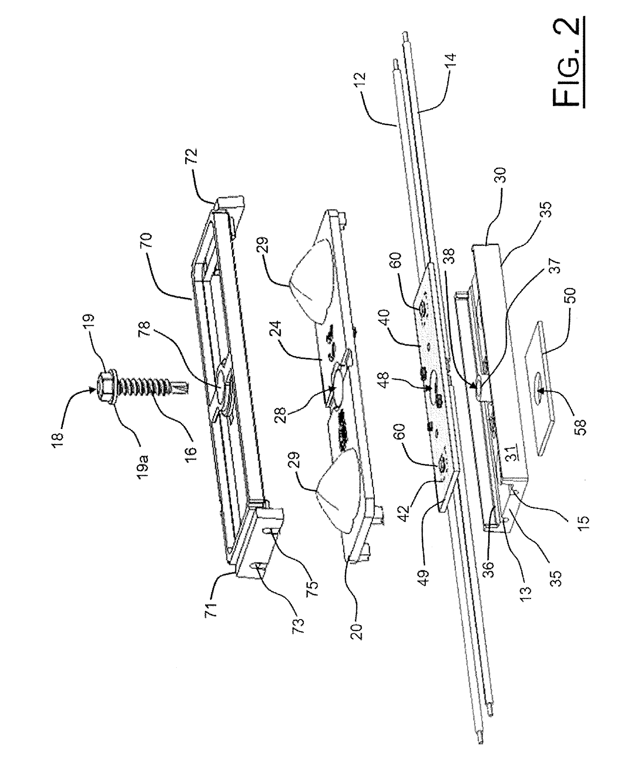
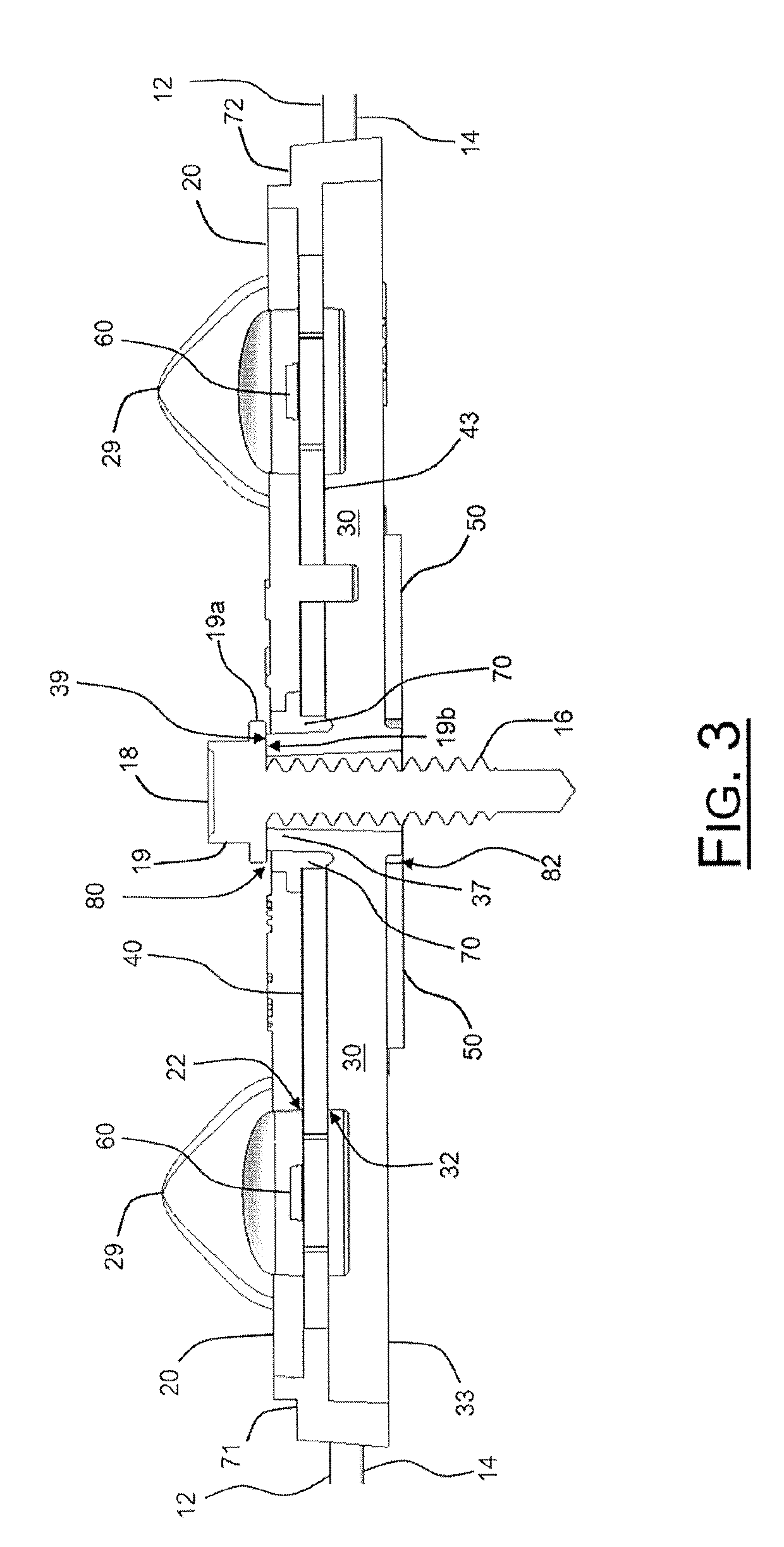
[0016]The present disclosure enables a durable LED light engine 10 that may be used for illuminating signage. Turning first to FIG. 1, there is represented an assembled LED light engine 10. As shown in FIG. 1, the top of the LED light engine 10 is a top enclosure 20. Included in and integrated with the top enclosure 20 are lenses 29. These lenses 29 are located over the LEDs 60 (shown in FIG. 2 and FIG. 3). Lenses 29 are spaced apart from one another on the surface of LED light engine 10. The placement of lenses 29 may allow for more uniform illumination when multiple LED light engines 10 are connected to one another. In particular lighting configurations in which multiple LED light engines are connected in a string, the placement of lenses 29 in top enclosure 20 allows for the optic spacing to be the same between LED light engines 10 as it is on one particular LED light engine 10.

[0017]Extending from the ends of the LED light engine 10 are insulated wires 12, 14. These insulated wi...


PUM


Abstract

A durable LED light engine includes a printed circuit board including LEDs mounted thereon positioned between a top enclosure and a bottom enclosure. Once assembled together, the combination of the top enclosure, the printed circuit board and the bottom enclosure are held together with a molding material. The top enclosure includes one or more integrated lenses for directing the illumination of the LEDs. The LED light engine may be mounted to a surface using a fastener passing through the combination of the top enclosure, the printed circuit board, and the bottom enclosure in the assembled LED light engine.

Description

CLAIM OF PRIORITY TO PRIOR APPLICATION[0001]The present application claims the benefit of prior filed U.S. Provisional Application, Ser. No. 62 / 584,224, filed Nov. 10, 2017. By this reference, the full disclosure, including the drawings and any claims, of U.S. Provisional Application, Ser. No. 62 / 584,224, is incorporated herein as though now set forth in its entirety.BACKGROUND1. Technical Field[0002]The disclosed invention relates to a device for using light emitting diodes (“LED”) to illuminate signage. More particularly, the present invention relates to a light engine which is attached to other similar light engines to form a string of light engines typically used for retail and commercial sign illumination but may be used for interior lighting, point of sale lighting, and merchandising displays.2. Related Art[0003]Conventional flexible lighting systems that incorporate strings of LED light engines are typically used to provide illumination for cabinet or channel letter signs. Su...

Claims


Application Information

Patent Timeline
IPC IPC(8): F21V19/00F21V5/04F21V23/00F21V31/00H05K1/18H05K7/14G09F13/22
CPCF21V19/0055F21V5/04F21V23/001F21V31/005H05K1/181H05K7/1427G09F13/22F21Y2115/10H05K2201/10106H05K2201/10409H05K2201/10121G09F2013/222G09F13/0404H05K3/284H05K2201/09063F21K9/20
Inventor GORMAN, AARONHONG, QILANKFORD, GRAY
Owner GENERAL LED OPCO LLC
Why Eureka
Try Eureka