Circuit for preventing surge and electronic apparatus having the same

a technology for electronic devices and circuits, applied in emergency protective circuit arrangements, emergency protective arrangements for limiting excess voltage/current, electric devices, etc., can solve problems such as damage to electronic devices' internal circuits, damage to electronic devices, and greatest damage to voltage, so as to effectively lower residual voltage

Inactive Publication Date: 2019-05-16
PEGATRON
View PDF1 Cites 3 Cited by
  • Summary
  • Abstract
  • Description
  • Claims
  • Application Information

AI Technical Summary

Benefits of technology

[0005]In view of the above, the application provides a circuit for preventing surge and an electronic apparatus having the same which can discharge a surge voltage on a signal path of the electronic apparatus and effectively lower a residual voltage on the signal path.
[0012]To sum up, in the circuit for preventing surge and the electronic apparatus having the same provided by the embodiments of the application, the transient surge voltage on the signal path of the electronic apparatus can be discharged, and the residual voltage remained on the signal path can be effectively lowered. Therefore, the device body is prevented from being damaged due to that the residual voltage on the signal path is excessively high.

Problems solved by technology

The surge voltage causes the greatest damage when the surge voltage is directly injected into the product.
As long as an electronic apparatus is connected to an external signal cable, the electronic apparatus is likely to be damaged as affected by the transient surge voltage on the cable.
Nevertheless, after an existing surge protection circuit discharges a surge high voltage, an excessively high residual voltage may still exist on the input path, and such excessively high residual voltage can still cause damages to the internal circuits of the electronic apparatus.

Method used


Image

  • Circuit for preventing surge and electronic apparatus having the same
  • Circuit for preventing surge and electronic apparatus having the same
  • Circuit for preventing surge and electronic apparatus having the same

Examples


Embodiment Construction

[0020]In order to make the application more comprehensible, several embodiments are described below as examples of implementation of the application. In addition, wherever possible, identical or similar reference numerals stand for identical or similar elements / components in the drawings and the embodiments.

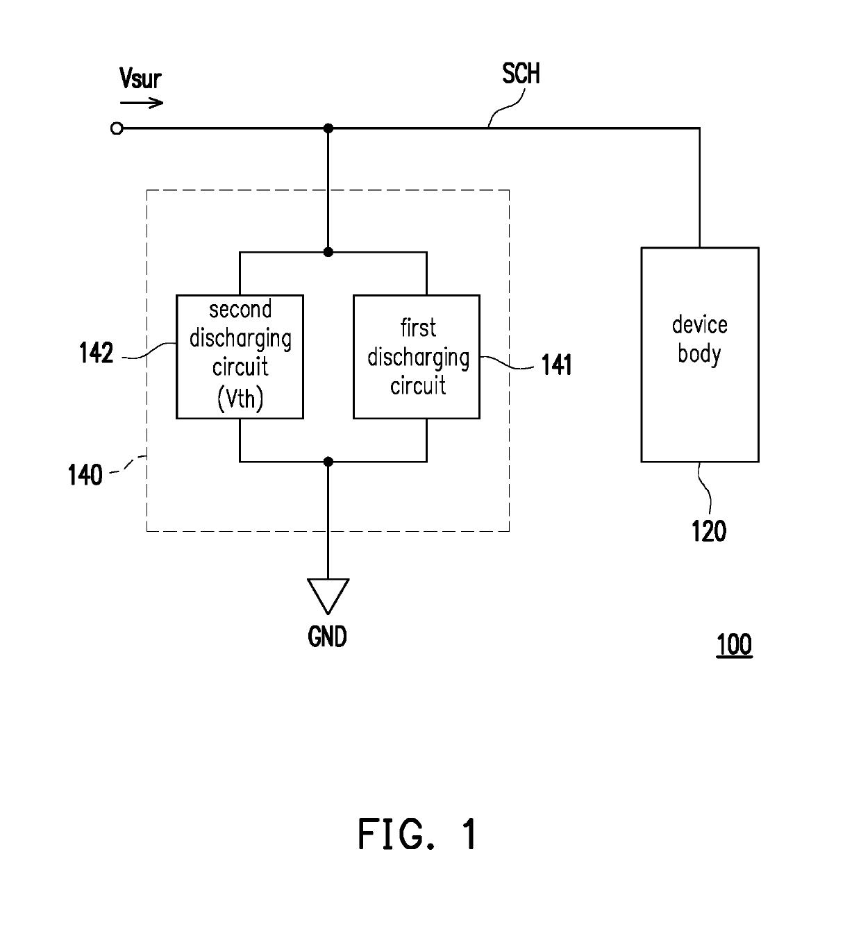
[0021]With reference to FIG. 1, FIG. 1 is a schematic circuit block diagram illustrating an electronic apparatus according to an embodiment of the application. In an embodiment of the application, an electronic apparatus 100 may be, for example, a personal computer, a power supplier, or a cable modem and the like, but the application is not limited thereto. The electronic apparatus 100 may include a device body 120 and a circuit for preventing surge 140. The device body 120 includes a circuit configured to perform a main function of the electronic apparatus 100. The device body 120 is coupled to a signal path SCH. In an embodiment of the application, the signal path SCH may be co...


PUM


Abstract

A circuit for preventing surge and an electronic apparatus having the same are provided. The circuit for preventing surge is configured to serve as a surge discharging path of the signal path so as to protect the device body. The circuit for preventing surge includes first and second discharging circuits. The first discharging circuit is coupled between the signal path and a ground terminal. The first discharging circuit is turned on in response to a transient surge voltage on the signal path so as to discharge the transient surge voltage to be a first surge voltage. The second discharging circuit is connected to the first discharging circuit in parallel. When a voltage difference between the first surge voltage and a voltage of the ground terminal is greater than or equal to a threshold voltage, the second discharging circuit is turned on to discharge the first surge voltage.

Description

CROSS-REFERENCE TO RELATED APPLICATION[0001]This application claims the priority benefit of Taiwan application serial no. 106139706, filed on Nov. 16, 2017. The entirety of the above-mentioned patent application is hereby incorporated by reference herein and made a part of this specification.BACKGROUNDTechnical Field[0002]The application relates to a protection circuit. More particularly, the application relates to a circuit for preventing surge and an electronic apparatus having the same.Description of Related Art[0003]A surge voltage may influence a product (e.g., a computer or a telephone and the like) itself through a power line or a ground path, and the extent and scope of such influence may vary according to the invasion path and the amount of energy. The surge voltage causes the greatest damage when the surge voltage is directly injected into the product. As long as an electronic apparatus is connected to an external signal cable, the electronic apparatus is likely to be dama...

Claims


Application Information

Patent Timeline
Patent Type & Authority Applications(United States)
IPC IPC(8): H02H9/06H02H9/04
CPCH02H9/06H02H9/044H02H9/042
Inventor HSIN, CHENG-CHANGTSAO, WEI-CHUNLIAO, HAN-CHIANG
Owner PEGATRON
Why Eureka
Try Eureka