
Unmanned automated hook coupling device

a technology of hook-fastening device and unmanned technology, which is applied in the direction of launching weapons, instruments, transportation and packaging, etc., can solve the problems of excessive system components, difficulty in workers' fastening of crane hooks, and broken video devices of hook-fastening devices, etc., to achieve easy traceability and accurate unloading

Active Publication Date: 2019-05-23
VESSEL AEROSPACE CO LTD
View PDF0 Cites 11 Cited by
  • Summary
  • Abstract
  • Description
  • Claims
  • Application Information

AI Technical Summary

Benefits of technology

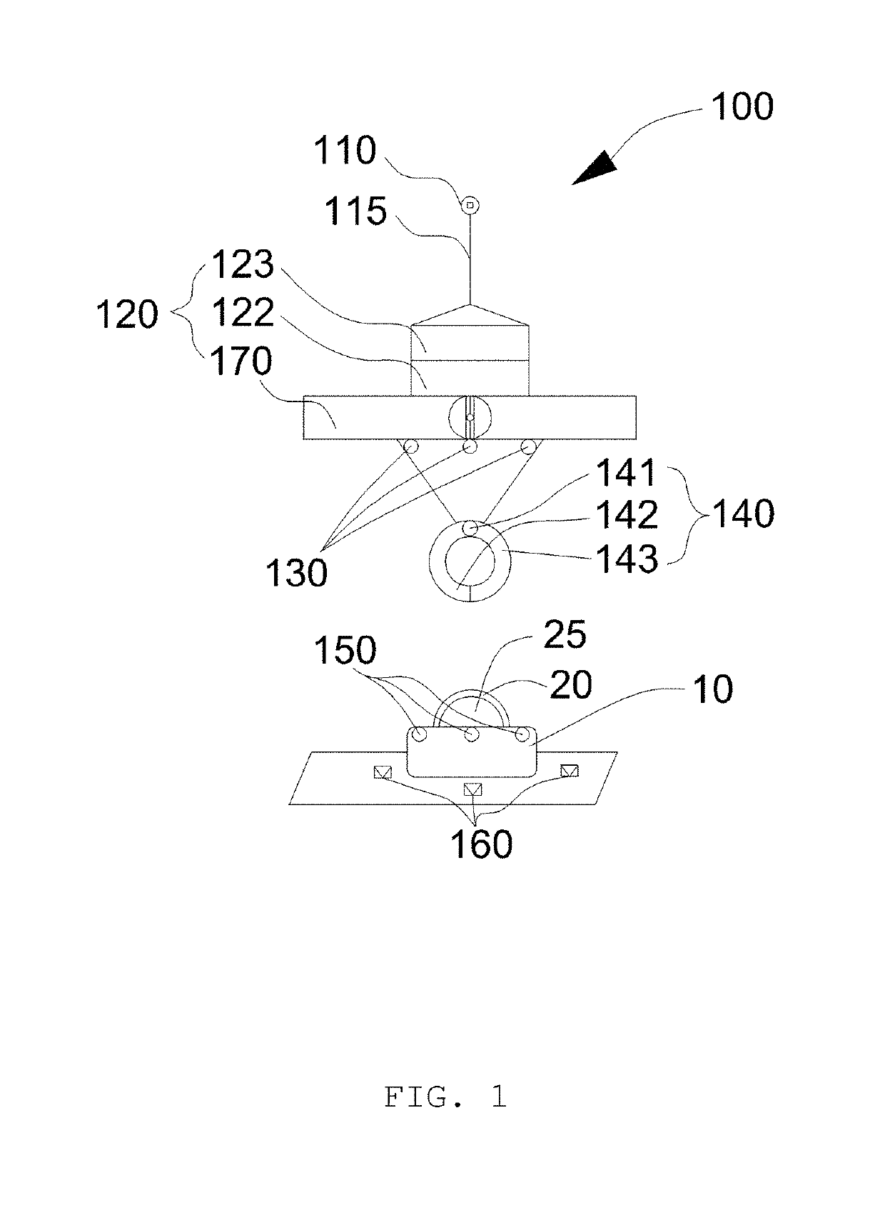
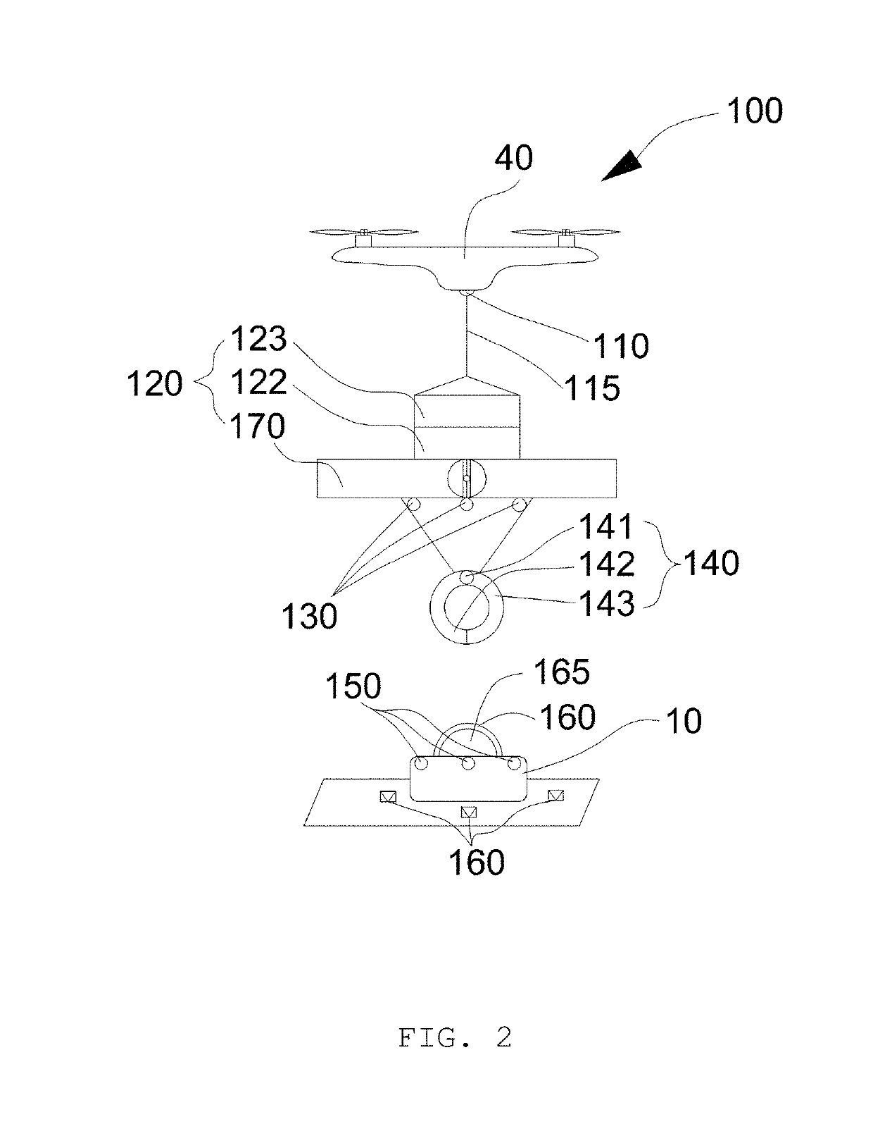
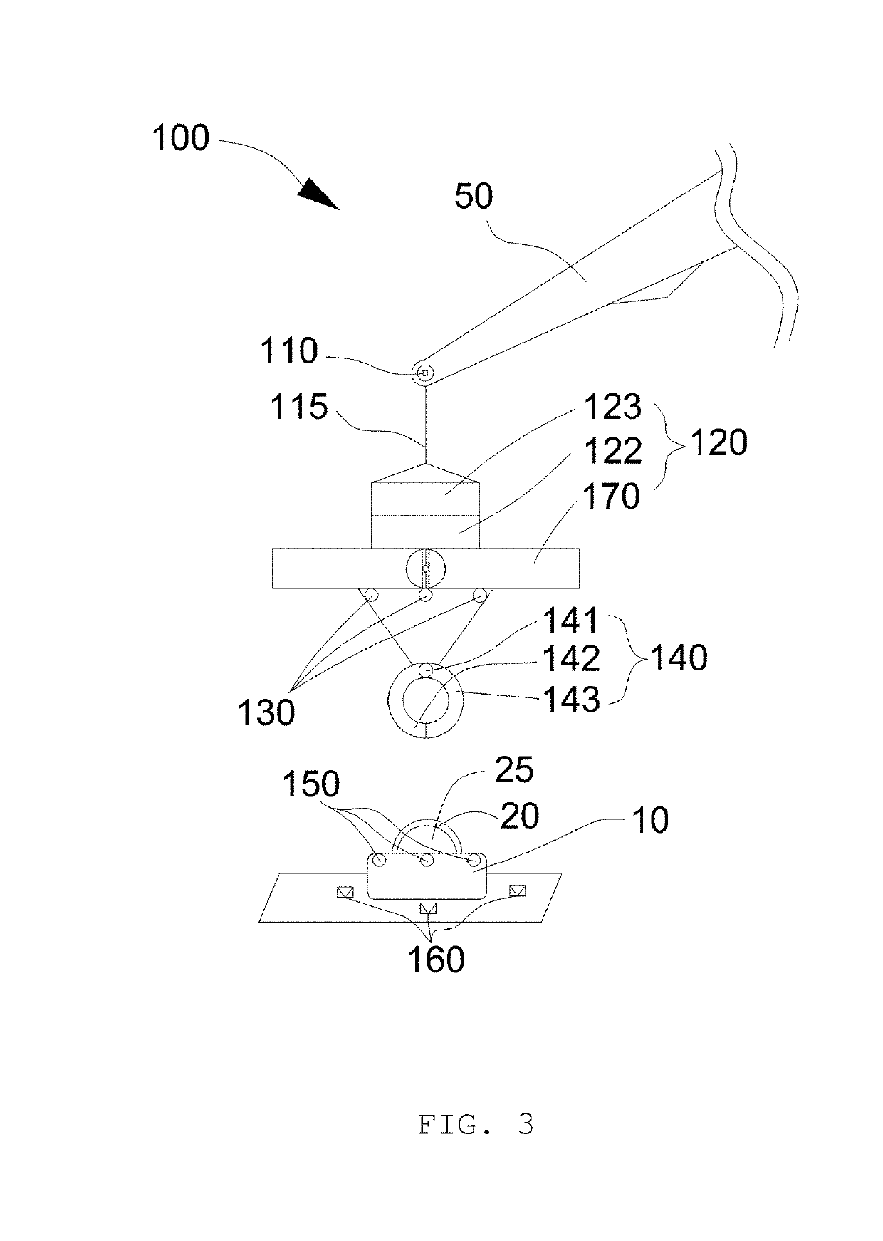
This patent describes a hook-fastening device that can be attached to a crane or helicopter to automatically fasten a hook to an object. The device includes a coupler, a propulsion unit, a transmitter, a receiver, hook pliers, and an unloading transmitter. The coupler attaches to the hoisting unit, and the propulsion unit moves the hoisting unit around the object to make it easier to find the hook. The receiver receives the position signal from the transmitter on the object, and the unloading transmitter sends a signal to assist in accurately unloading the object. The device allows for quicker and safer attachment of objects to cranes without requiring a separate monitoring system.

Problems solved by technology

However, there are various types of crane hooks having significant weights, depending on the object to be hoisted, so it may be difficult for workers to fasten the crane hook to the object to be hoisted.
In such systems, a monitoring operation is necessary, and excessive system components increase construction costs, which are problematic.
In addition, the video device may be disposed adjacently to the hook, and an accident in which a hook-fastening device breaks the video device in the hook-fastening process may frequently occur.
Accordingly, maintenance of the video device may be difficult.
Furthermore, such systems may be unable to rapidly locate an object to be hoisted and to rapidly fasten the hook to the object to be hoisted, thereby causing problems in which the hook-fastening operation may be significantly slowed down and must be carried out by field personnel.

Method used


Image

  • Unmanned automated hook coupling device
  • Unmanned automated hook coupling device
  • Unmanned automated hook coupling device

Examples


first embodiment

[0091]Hereinafter, an unmanned automated hook-fastening device according to another embodiment of the present disclosure will be described with reference to the accompanying drawings. In the following, descriptions of some features will be omitted when they are identical to those of the above-described first embodiment of the present disclosure.

second embodiment

[0092]FIG. 10 is a view illustrating a structure of an unmanned automated hook-fastening device according to the present disclosure.

[0093]Referring to FIG. 10, an unmanned automated hook-fastening device 200 includes a global positioning system (GPS) receiver 280.

[0094]The PGS receiver 280 may be disposed on an object 30 to be hoisted, and receive GPS signals from a plurality of satellites to locate the object.

[0095]According to the above-described configuration, the position of the object 30 is determined on the basis of GPS signals received by the GPS receiver 280 from the satellites, and the unmanned automated hook-fastening device 200 performs a first movement so that hook pliers 240 are adjacent to the object 30.

[0096]In this position, when a hoisting unit arrives at a location within a preset distance from the object 30 due to the first movement using the GPS receiver 280, the operation of the GPS receiver 280 is stopped.

[0097]In this position, the unmanned automated hook-fast...


PUM


Abstract

Disclosed is an unmanned automated hook-fastening device including a device coupler, a propulsion unit, a transmitter, a receiver, hook pliers, and an unloading transmitter. The propulsion unit adjusts the position of the hoisting unit with respect to the object, on the basis of the position signal transmitted by the transmitter and received by the receiver, and adjusts the position of the hoisting unit coupled to the object, on the basis of the position signal transmitted by the unloading transmitter and received by the receiver. It is possible to easily track the position of a hook of the object to be hoisted, automatically fasten the hook pliers to the hook, and automatically fasten the hook to a crane without a monitoring system.

Description

TECHNICAL FIELD[0001]The present disclosure relates to an unmanned automated hook-fastening device.BACKGROUND ART[0002]A crane is a conveying machine for hoisting and moving various types of freight vertically and laterally in a variety of sites.[0003]Such a crane uses a crane hook as a lifting tool. The hook is a fastening tool configured to be reliably fastened to an object to be hoisted, so that the crane can move the object to be hoisted to a loading location.[0004]That is, the crane hook connects the crane and the object to be hoisted. When the crane is to move the object to be hoisted, the first operation is to fasten the crane hook to the object be hoisted.[0005]When fastening the crane hook to the object to be hoisted, the crane hook must be correctly fastened to the object so that the object cannot be detached from the crane hook while the crane is moving the object.[0006]However, there are various types of crane hooks having significant weights, depending on the object to ...

Claims


Application Information

Patent Timeline
Patent Type & Authority Applications(United States)
IPC IPC(8): B64C39/02B64C27/08B64D1/02G01S19/42B66C1/34
CPCB64C39/024B64C27/08B64D1/02G01S19/42B66C1/34B64C2201/024B64C2201/108B64C2201/162B64C2201/128B66C13/48B66C13/08B66C13/46B64D1/22B64C27/00G01S5/30G01S19/14B66C13/40
Inventor KUK, TAE SEUNG
Owner VESSEL AEROSPACE CO LTD
Learn More