Method for Producing Lamination Stacks and Facility for Performing the Method

a technology of lamination and stacks, which is applied in the direction of material gluing, manufacturing stator/rotor bodies, fastening means, etc., can solve the problems of inability to establish sufficient adhesion between the adhesive and the insulation surface, the elaborate design of the application head of such piezo valves, and the corresponding cost, so as to achieve the effect of reliably processing particularly thin workpieces

Active Publication Date: 2019-05-23
FEINTOOL SYST PARTS SACHSENHEIM GMBH
View PDF0 Cites 2 Cited by
  • Summary
  • Abstract
  • Description
  • Claims
  • Application Information

AI Technical Summary

Benefits of technology

[0015]In the first inventive method, the laminations are realized annularly. They may be punched out of a sheet metal strip or a sheet metal plate or produced thereof in a different way, particularly by means of laser cutting. During the application of the adhesive, the annular laminations are positioned in the region of the application head in such a way that the lamination is located in the application area of the application head. The annular lamination is rotated about its axis during the application of the adhesive. In this way, the entire upper side of the lamination passes through the application area of the application head. Consequently, the complete upper side of the annular lamination can be provided with adhesive over its entire surface with a simple constructive design of the application head. Only a small number of application nozzles is required in the application head in order to provide the annular lamination with adhesive over its circumference. Depending on the respective requirements, however, it is also possible to provide only part of the surface of the annular lamination with the adhesive.
[0017]It is advantageous if the lamination and / or the application head are respectively rotated or moved in a uniform fashion. In this way, the adhesive can be easily applied onto the desired lamination areas over the circumference of the annular lamination. In addition, it is correspondingly simple to control the motion of the lamination and / or the application head.
[0029]The inventive method particularly makes it possible to apply the adhesive in such a quantity that the adhesive surface area on the upper side of the lamination amounts to at least approximately 50% of the overall surface area of the upper side of the lamination. This large proportion of adhesive results in the laminations being reliably connected to one another within the stack. This large adhesive surface area also does not require an elaborate construction of the application head.
[0033]It is advantageous if the laminations are respectively transported between the individual positions by 90°.
[0034]The inventive method makes it possible to reliably process particularly thin workpieces that usually have a thickness of less than 1 mm. Particularly laminations with different quality, thickness, properties and coating can be processed. It is even possible to use laminations with different quality, thickness, properties and coating within the stack.
[0035]In the inventive system, at least one station, in which the laminations are cleaned and / or activated and / or provided with adhesive, is arranged downstream of the punching tool, in which the laminations are punched out. In this context, it would be possible that the system features a separate station for each operation. However, all three operations, namely cleaning, activating and applying the adhesive, can also be carried out in a single station. Since this station is not arranged in the punching tool, but rather outside thereof, the punching tool remains free of potential contaminations that could occur while the laminations are cleaned and / or activated and / or provided with the adhesive.

Problems solved by technology

An application head with such piezo valves therefore has an elaborate design and is correspondingly expensive.
This makes it impossible to establish sufficient adhesion between the adhesive and the insulation surface and / or to establish adhesion within the required time.

Method used


Image

  • Method for Producing Lamination Stacks and Facility for Performing the Method
  • Method for Producing Lamination Stacks and Facility for Performing the Method
  • Method for Producing Lamination Stacks and Facility for Performing the Method

Examples


Embodiment Construction

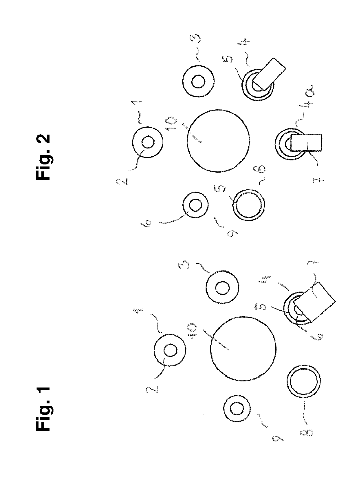
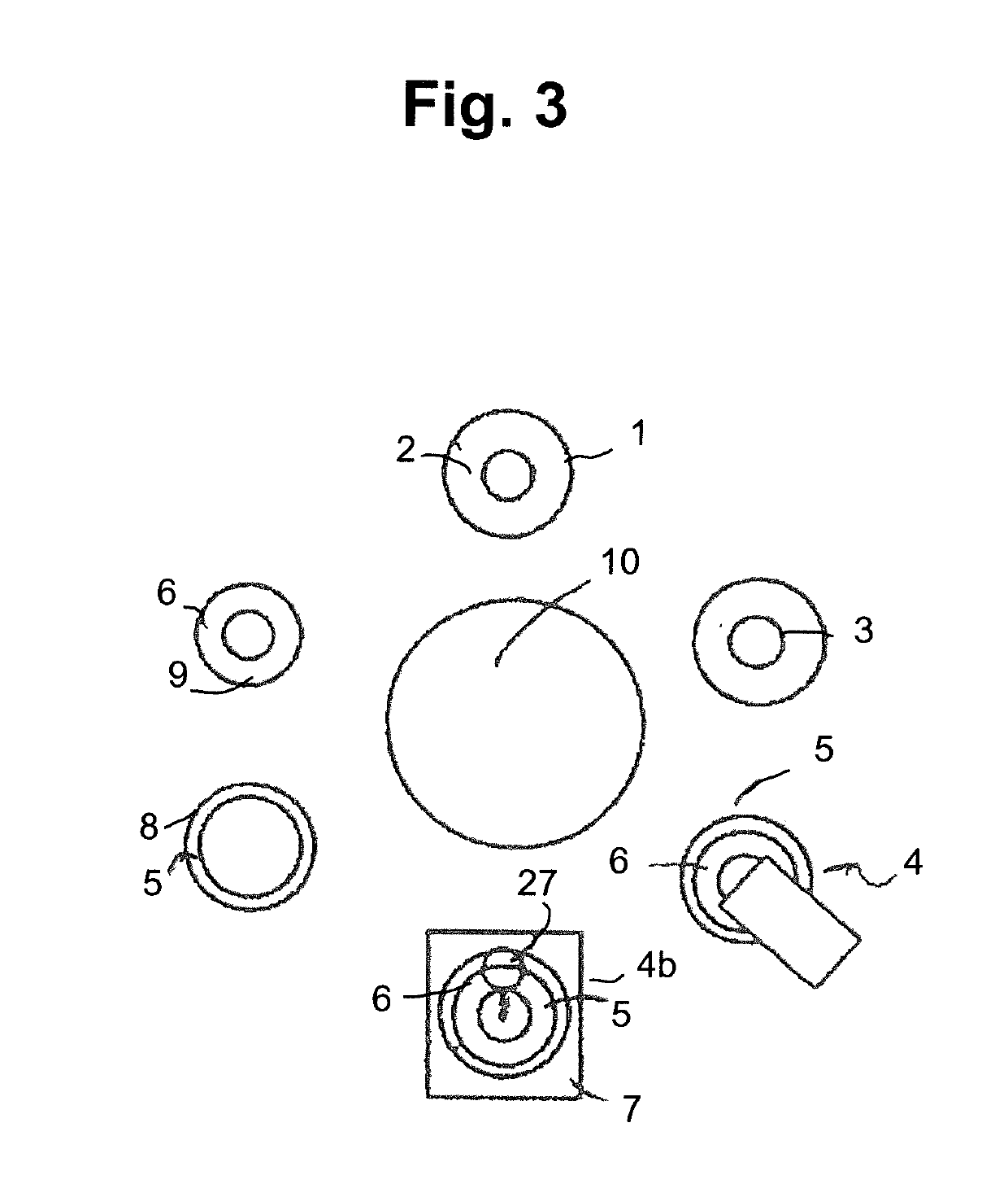
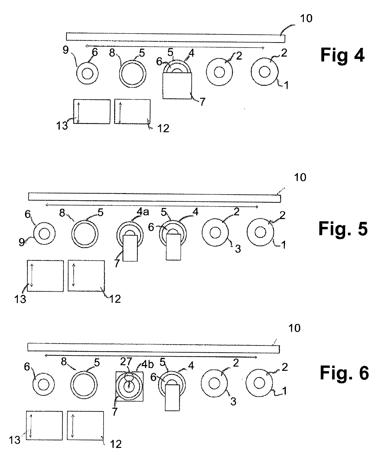
[0058]In the following description, it is explained with reference to different exemplary embodiments how laminations lying on top of one another within a stack can be solidly connected to one another by means of at least one adhesive. The systems and devices used in this case are realized in such a way that the individual laminations have a relatively large adhesive surface area that amounts, for example, to more than approximately 60% of the overall surface area of the lamination. In this case, the adhesive may be applied onto the respective lamination in a punctiform, linear or even planar fashion. The devices used for this large-surface adhesive application are characterized by a very simple and space-saving constructive design.

[0059]FIG. 1 shows a schematic illustration of an exemplary notching press in the form of a circular arrangement. This system has a first station 1, in which laminations 2 in the form of round sheet metal blanks are stored. A transport system 10 transport...


PUM

PropertyMeasurementUnit
thicknessaaaaaaaaaa
rotationaaaaaaaaaa
angleaaaaaaaaaa

Abstract

In a method for producing stacks of laminations, in which at least one adhesive is applied onto annular laminations with at least one application head and laminations are stacked into a stack of laminations, the lamination is rotated about its axis in the application area of the application head and / or the application head is moved about the axis of the lamination in order to apply the adhesive onto the lamination. A system for carrying out the method features at least one punching tool, with which laminations are punched out of a sheet metal material, wherein at least one station for cleaning and / or for activating and / or for applying an adhesive onto the laminations is arranged downstream of the punching tool.

Description

CROSS-REFERENCE TO RELATED APPLICATIONS[0001]This application is a divisional application of U.S. application Ser. No. 14 / 941,866 having a filing date of 16 Nov. 2015, said application claiming a priority date of 17 Nov. 2014, based on prior filed German patent application No. 10 2014 017 149.3, the entire contents of the aforesaid United States application and the aforesaid German patent application being incorporated herein by reference.BACKGROUND OF THE INVENTION[0002]The invention pertains to a method for producing stacks of laminations in which at least one adhesive is applied onto annular laminations with at least one application head and laminations are stacked into a stack of laminations or in which the laminations are punched out of a sheet metal strip and at least one adhesive is applied onto the laminations with at least one application head, wherein the laminations provided with the adhesive are stacked into a stack of laminations, as well as to a system for carrying out...

Claims


Application Information

Patent Timeline
Patent Type & Authority Applications(United States)
IPC IPC(8): H02K15/02F16B11/00
CPCH02K15/02F16B11/006Y10T29/49055Y10T29/49009Y10T29/49078Y10T29/5317Y10T29/53143H02K15/12
Inventor BOKER, BJORN
Owner FEINTOOL SYST PARTS SACHSENHEIM GMBH
Why Eureka
Try Eureka