OLED lighting apparatus

a technology of light-emitting diodes and lighting apparatuses, which is applied in the field of display devices, can solve the problems of reducing color rendering properties, reducing luminous efficacy, and very low energy efficiency of incandescent lamps, and achieves the effect of improving reliability and reducing manufacturing costs

Active Publication Date: 2019-05-30
LG DISPLAY CO LTD
View PDF0 Cites 2 Cited by
  • Summary
  • Abstract
  • Description
  • Claims
  • Application Information

AI Technical Summary

Benefits of technology

[0008]An aspect of the present disclosure is aimed at providing an OLED lighting apparatus which can achieve both improvements in reliability and reduction in manufacturing costs.
[0010]Thus, the OLED lighting apparatus according to the aspect of the present disclosure includes a via electrode passing through the encapsulation layer to be connected to a pad, thereby improving reliability of an organic light emitting device while achieving reduction in manufacturing costs.
[0020]Further, in the OLED lighting apparatus according to the aspect of the present disclosure, since tape automated bonding is performed after the pad disposed in the non-active area of the buffer layer is stably secured by the encapsulation layer, it is possible to omit a substrate formed of a transparent PI film, which would otherwise be disposed under the buffer layer, thereby reducing manufacturing costs.
[0021]Furthermore, since the OLED lighting apparatus according to the present disclosure does not require such a substrate, a method of forming auxiliary wires, an organic light emitting device and the like can be executed at a high temperature exceeding 350° C., thereby improving reliability of the organic light emitting device.
[0022]Furthermore, in the OLED lighting apparatus according to the present disclosure, the buffer layer formed as an inorganic layer such as SiOx or SiNx is also exposed to the high temperature process exceeding 350° C. and thus can have improved properties in terms of strength and hardness.

Problems solved by technology

The incandescent lamps have a problem of a very low energy efficiency, despite a high color rendering index, and the fluorescent lamps have a problem of a low color rendering index and contain mercury causing environmental pollution, despite a good energy efficiency.
Accordingly, a method of obtaining white light by combining a red LED with a green LED and a blue LED has a problem of reduction in luminous efficacy.
Such a method also has a problem of reduction in color rendering properties due to a small width of an emission peak of each LED.
However, such a lighting apparatus configured to emit white light through combination of the blue LED with the yellow phosphors has limited luminous efficacy due to low luminous efficacy of the yellow phosphors.

Method used


Image

  • OLED lighting apparatus
  • OLED lighting apparatus
  • OLED lighting apparatus

Examples


Embodiment Construction

[0033]Hereinafter, aspects of the present disclosure will be described in detail with reference to the accompanying drawings. It should be understood that the present disclosure is not limited to the following aspects and may be embodied in different ways, and that the aspects are given to provide complete disclosure of the present disclosure and to provide thorough understanding of the present disclosure to those skilled in the art. Description of known functions and constructions which can unnecessarily obscure the subject matter of the present disclosure will be omitted. Like components will be denoted by like reference numerals throughout the specification.

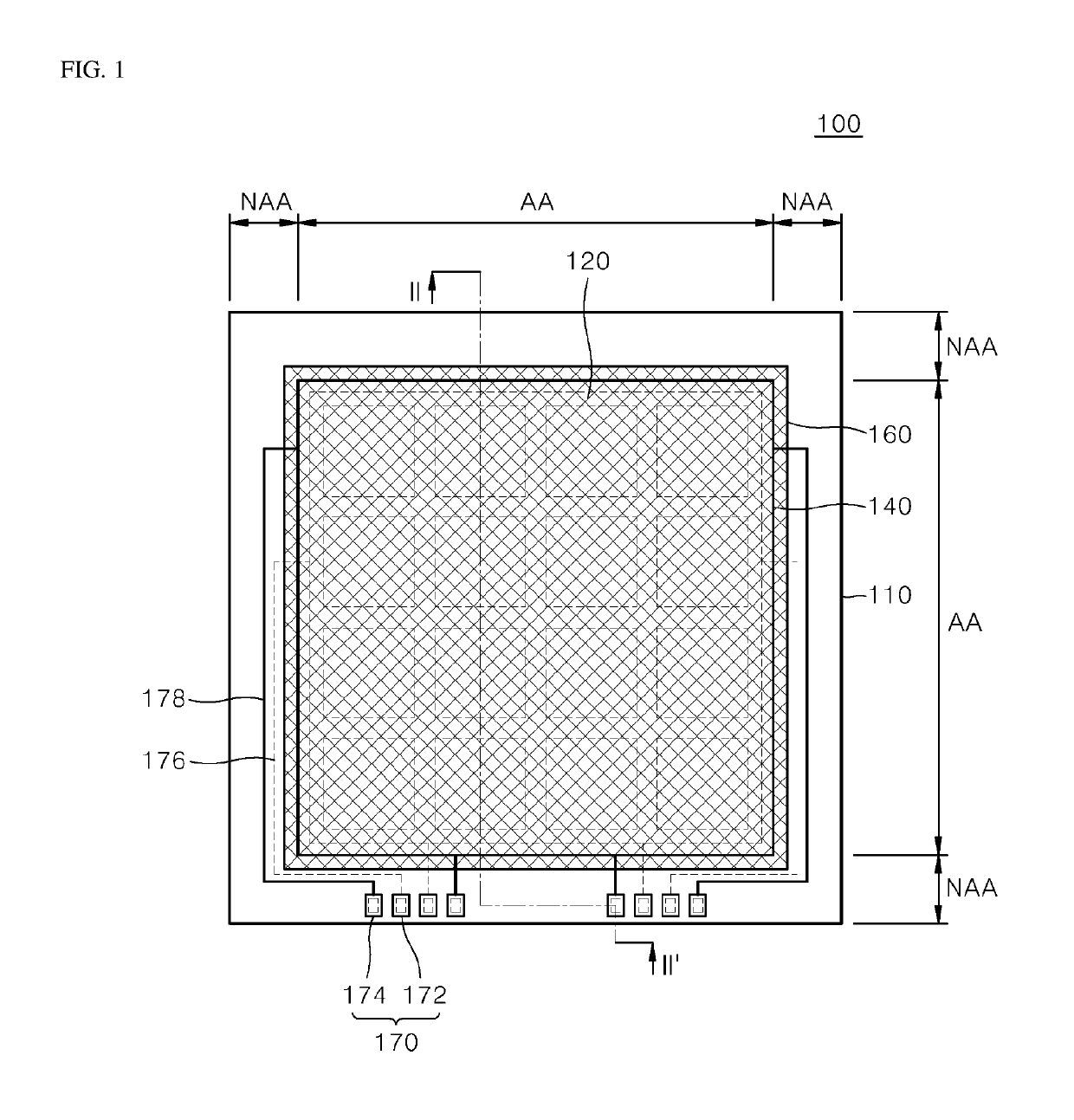
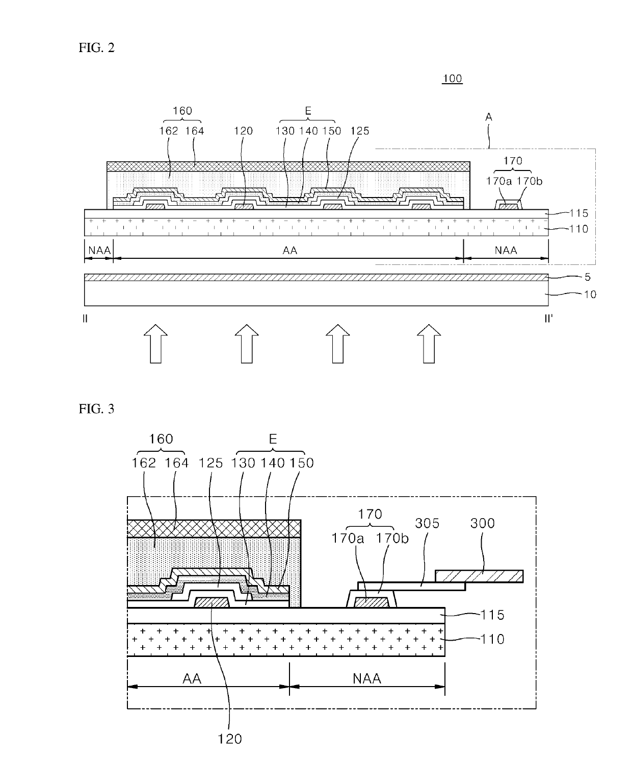
[0034]Now, an OLED lighting apparatus according to a first aspect of the present disclosure will be described in detail with reference to the accompanying drawings. FIG. 1 is a plan view of an OLED lighting apparatus according to a first aspect of the present disclosure and FIG. 2 is a cross-sectional view taken along line II-...


PUM


Abstract

Disclosed herein is an OLED lighting apparatus which can achieve both improvement in reliability and reduction in manufacturing cost. In the OLED lighting apparatus, an encapsulation layer is disposed over the active area and the non-active area on a buffer layer, such that a pad disposed in the non-active area of the buffer layer can be stably secured by the encapsulation layer bonded thereto. Accordingly, upon tape automated bonding between an FPCB substrate with a COF tape attached thereto and a via electrode, the COF tape does not directly contact the pad but contacts the via electrode connected to the pad, particularly a connection terminal of the via electrode disposed on an upper surface of the encapsulation layer, thereby establishing electrical connection between the FPCB substrate and the via electrode. In this way, the connection terminal of the via electrode is electrically connected to the FPCB substrate via the COF tape, whereby a signal from the outside can be applied to the pad connected to the via electrode.

Description

CROSS-REFERENCE TO RELATED APPLICATION[0001]This application claims the benefit of the Korean Patent Application No. 10-2017-0159846 filed on Nov. 28, 2017, which is hereby incorporated by reference in its entirety.BACKGROUNDField of the Disclosure[0002]The present disclosure relates to a display device, and more particularly, to an organic light emitting diode (OLED) lighting apparatus. Although the present disclosure is suitable for a wide scope of applications, it is particularly suitable for improving reliability of the organic light emitting diode (OLED) lighting apparatus and reducing manufacturing costs.Description of the Background[0003]Currently, fluorescent lamps and incandescent lamps are mainly used as a lighting apparatus. The incandescent lamps have a problem of a very low energy efficiency, despite a high color rendering index, and the fluorescent lamps have a problem of a low color rendering index and contain mercury causing environmental pollution, despite a good en...

Claims


Application Information

Patent Timeline
Patent Type & Authority Applications(United States)
IPC IPC(8): H01L51/52H01L27/32G09G3/3225
CPCH01L51/5203H01L51/5237H01L27/3276G09G3/3225Y02E10/549Y02P70/50H10K71/80H10K50/814H10K50/844H10K2102/311H10K50/88F21Y2115/15H10K30/20H10K50/805H10K50/84H10K59/131
Inventor LEE, KYU-HWANGSONG, TAEJOONKIM, CHULHOLEE, HWANKEON
Owner LG DISPLAY CO LTD
Why Eureka
Try Eureka