
Ventricular assist system and blood pump controller

Active Publication Date: 2019-06-06
SUN MEDICAL TECH RES
View PDF0 Cites 6 Cited by
  • Summary
  • Abstract
  • Description
  • Claims
  • Application Information

AI Technical Summary

Benefits of technology

The patent text describes a demand for a blood pump controller and ventricular assist system that are small and portable. The invention aims to provide a blood pump controller that is easy to carry and use. The invention also includes a separation detection means to detect if the first and second sub controllers are connected or separated. This feature helps to improve the overall performance and reliability of the blood pump controller.

Problems solved by technology

Accordingly, when a user of the ventricular assist system who has a heart failure carries the blood pump controller 19 when he goes out, the size and the weight of such a blood pump controller 19 imposes a large burden on the user.

Method used


Image

  • Ventricular assist system and blood pump controller
  • Ventricular assist system and blood pump controller
  • Ventricular assist system and blood pump controller

Examples


embodiment 1

1. Configuration of Ventricular Assist System 1 and Blood Pump Controller 11 According to Embodiment 1

(1) Ventricular Assist System 1

[0081]The ventricular assist system which compensates for a part of a function of a heart for sustaining the life of a patient (user) until patient receives the heart implantation.

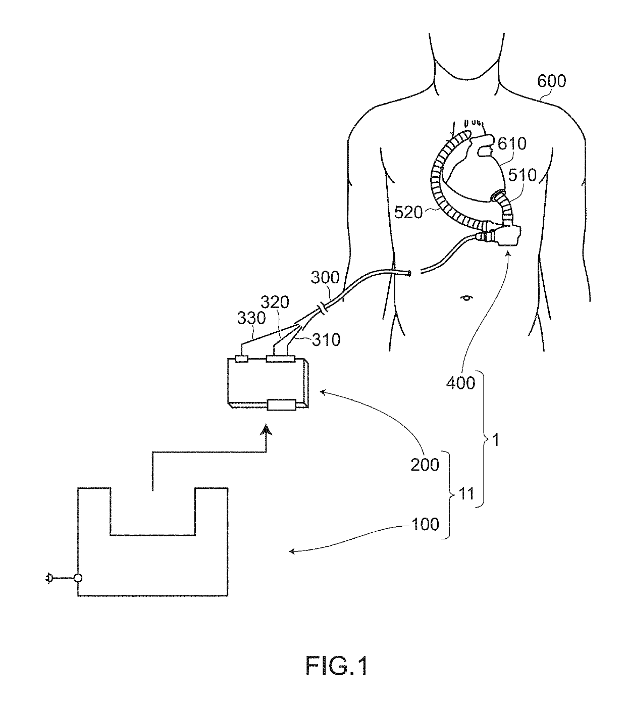
[0082]FIG. 1 is a schematic view for describing the ventricular assist system 1 and the blood pump controller 11 used in the ventricular assist system 1 according to the embodiment 1.

[0083]As shown in FIG. 1, the ventricular assist system 1 includes a blood pump 400 embedded in a body of a user 600, an artificial blood vessel 510 which connects the blood pump 400 and a left ventricle (not shown in the drawing) of an actual heart 610 of the user 600; an artificial blood vessel 520 for returning blood from the blood pump 400 to a living body of the user; the blood pump controller 11 disposed outside the body of the user 600, an up tube 310 and a down tube 320 which connect the ...

embodiment 2

[0161]Next, a ventricular assist system 2 (to be more specific, a blood pump 400a) according to the embodiment 2 is described with reference to FIG. 4A to FIG. 5. The description of constitutional elements of the embodiment 2 which are substantially equal to the corresponding constitutional elements of the embodiment 1 is omitted.

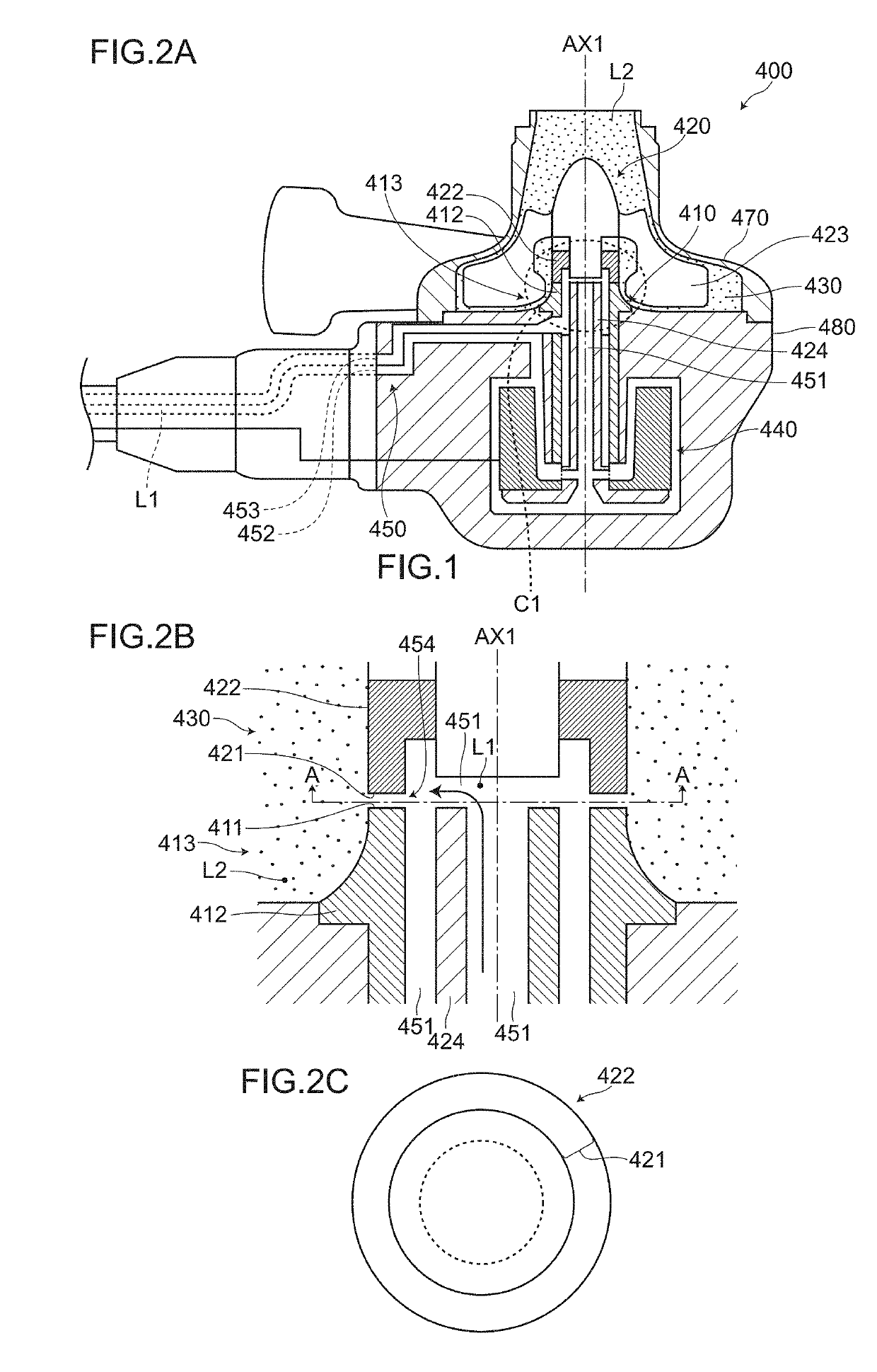
[0162]FIG. 4A to FIG. 4D are views for describing the blood pump 400a according to the embodiment 2. FIG. 4A is a cross-sectional view of a main part showing a part of the blood pump 400a corresponding to the part surrounded by a dotted line C1 shown in FIG. 2A in an enlarged manner. FIG. 4B is a plan view of a rotary side slide member 422 taken along a line A-A in FIG. 4A as viewed in an arrow direction. FIG. 4C is an enlarged view showing a portion surrounded by a dotted line R1 in FIG. 4B in an enlarged manner. FIG. 4D is a cross-sectional view of dynamic pressure grooves 460 / 462 taken along a line B-B in FIG. 4C as viewed in an arrow direction.

[0163]FIG...

embodiment 3

[0177]Next, a ventricular assist system 3 and a blood pump controller 13 according to the embodiment 3 are described with reference to FIG. 6A and FIG. 6B. The description of constitutional elements of the embodiment 3 which are substantially equal to the corresponding constitutional elements of the embodiments 1 and 2 is omitted.

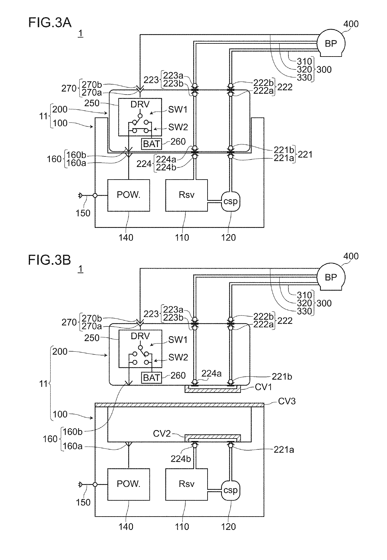
[0178]FIG. 6A and FIG. 6B are block diagrams for describing the ventricular assist system 3 and the blood pump controller 13 according to the embodiment 3. FIG. 6A is a block diagram showing a state where a second sub controller 203 is connected to a first sub controller 100a (a docked state). FIG. 6B is a view showing a state where the second sub controller 203 is separated from the first sub controller 100a.

[0179]The ventricular assist system 3 and the blood pump controller 13 according to the embodiment 3 have basically substantially the same configuration as the ventricular assist system 1 and the blood pump controller 11 according to the embodiment 1 ...


PUM


Abstract

A ventricular assist system and a blood pump controller including a blood pump usable in a state where a first slide surface and a second slide surface are brought into contact with each other, and a cool sealing liquid is supplied to a gap formed between the first slide surface and the second slide surface; a first sub controller having a first cool sealing liquid reservoir, a cool sealing liquid pump, a first pipe joint upstream side, and a fourth pipe joint downstream side; and a second sub controller having a blood pump drive circuit, a battery, a first pipe joint downstream side, a second pipe joint upstream side, a third pipe joint downstream side, and a fourth pipe joint upstream side. The first sub controller and the second sub controller are detachably connected by a first pipe joint and a fourth pipe joint.

Description

BACKGROUND OF THE INVENTION1. Field of the Invention[0001]The present invention relates to a ventricular assist system and a blood pump controller.2. Description of the Related Art[0002]There has been known a so-called centrifugal type blood pump which supplies blood into a body of a user using a centrifugal force generated by the rotation of an impeller (see JP-A-2014-128516, for example).[0003]FIG. 14A to FIG. 14C are views for describing one example of a centrifugal type blood pump 409. FIG. 14A is a cross-sectional view showing the entire configuration of the blood pump 409. FIG. 14B is a cross-sectional view of a main part showing a portion of FIG. 14A surrounded by a dotted line C in an enlarged manner. FIG. 14C is a plan view of a rotary side slide member 922 taken along a line A-A in FIG. 14B as viewed in an arrow direction. FIG. 15 is a schematic view for describing a conventional ventricular assist system 9 and a conventional blood pump controller 19. FIG. 16 is a block di...

Claims


Application Information

Patent Timeline
IPC IPC(8): A61M1/10A61M1/12A61M60/178A61M60/232A61M60/237A61M60/416A61M60/554A61M60/592A61M60/81A61M60/829A61M60/876A61M60/878A61M60/88
CPCA61M1/1025A61M1/1031A61M1/1086A61M1/127A61M2205/3606A61M2205/366A61M2205/0216A61M60/824A61M60/829A61M60/148A61M60/81A61M60/232A61M60/878A61M60/592A61M60/554A61M60/88A61M60/237A61M60/416A61M60/178A61M60/876A61M60/422
Inventor KOIKE, NOZOMIKOBAYASHI, SHINJIKANEBAKO, HIDEKI
Owner SUN MEDICAL TECH RES
Features
  • Generate Ideas
  • Intellectual Property
  • Life Sciences
  • Materials
  • Tech Scout
  • Unparalleled Data Quality
  • Higher Quality Content
  • 60% Fewer Hallucinations
Learn More