
Method and device for measuring a distance to a target in a multi-user environment by means of at least one detector

a multi-user environment and detector technology, applied in the direction of measurement devices, instruments, using reradiation, etc., can solve the problems of interference with individual measurements, detection of wrong distances, and danger of detecting wrong distances

Active Publication Date: 2019-06-06
FASTREE3D
View PDF0 Cites 16 Cited by
  • Summary
  • Abstract
  • Description
  • Claims
  • Application Information

AI Technical Summary

Benefits of technology

The invention provides a way to measure how far a person's body is from a target in a crowded space. The method works by using sensors that measure how long it takes for light to travel to and from the target. This method is designed to be resistant to malicious people in the space who might try to interfere with the measurement.

Problems solved by technology

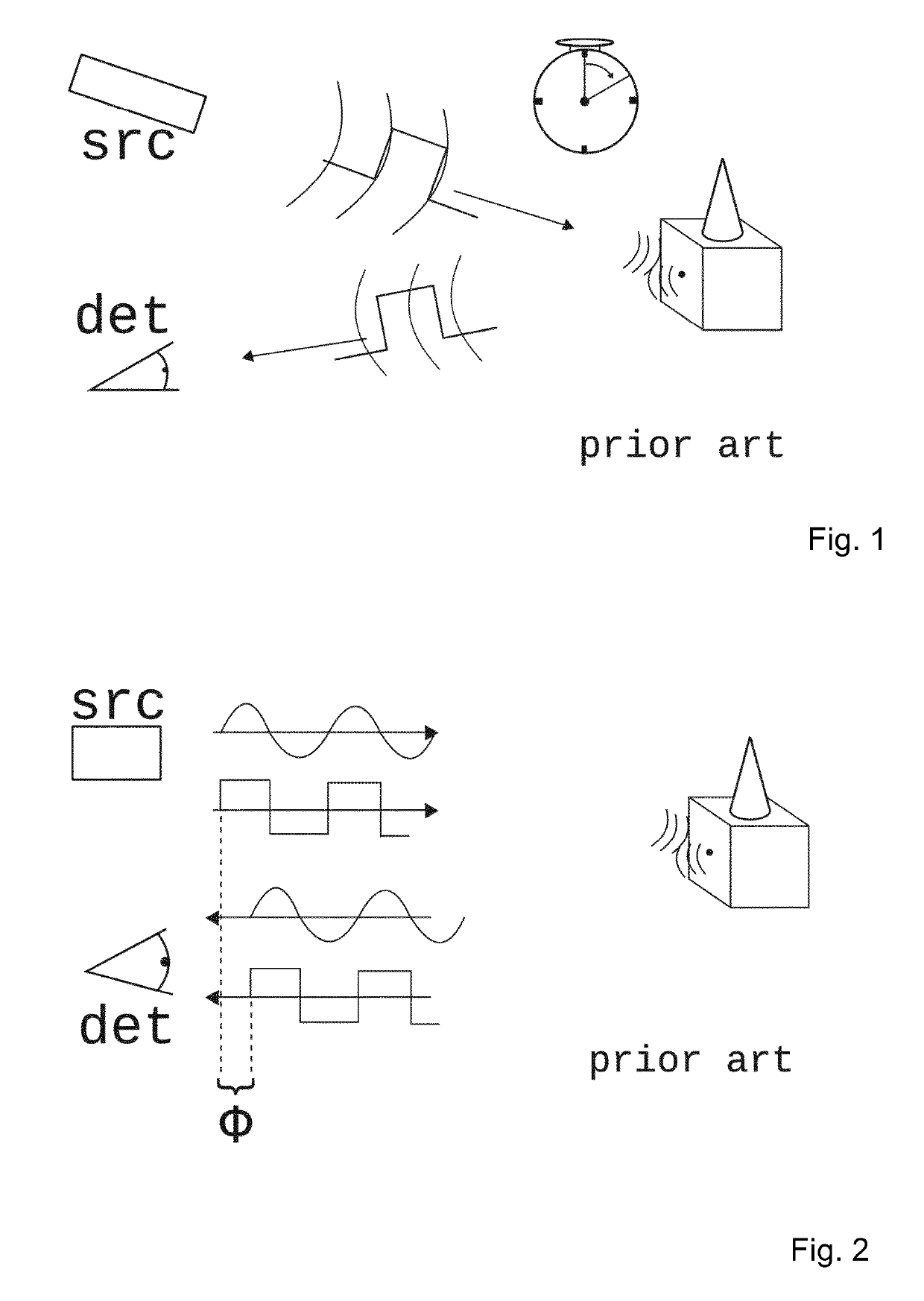
The presence of several of such TOF systems in the same environment—most noticeably when they are facing the same direction—may interfere with the individual measurements.
This interference can lead to the detection of wrong distances.
Detecting the wrong distance can be dangerous for example if the TOF system is supposed to observe the environment around an automated guided vehicle.
Nonetheless, these methods have several short comings.
The disadvantage in requiring a central coordination unit are increased costs and needed effort to install a multi-user environment.
It is potentially dangerous to rely on the cooperation of foreign systems, as for example different manufacturers could use different protocols.
And even if an industry wide standard is agreed upon, previous generation systems, or intentionally malicious participants, can jeopardize the multi-user environment.
These secondary systems are expected to pollute the measurement, by effecting wrong measurement values from time to time.
The inherent problem to such postprocessing solutions is the added latency: an accurate value can be reported only after N measurements.
Typically, this is an undesired property in applications that rely on real time data, such as for example in automotive.
Furthermore, if the probed target moves during these N measurements, i.e. the real distance is not the same for all those N single measurements, the postprocessing unit has to overcome additional difficulties.
In reality, the possibilities of such frequency / wavelength-multiplexing strategies are, however, very limited for a multi-user environment.
Secondly, lidar systems would have considerably more regulatory freedom, but realistic wavelength band pass filters limit the available number of options considerably.
Real random numbers are often not desired as they are not controllable and can bring in unfortunate dependencies and correlations.
This last point is particularly detrimental in non-cooperative multi-user environments.
For many other applications, however, this poses an undesired vulnerability.
Chaotic systems are still deterministic systems, in principle, but they depend heavily on the exact initial conditions, which makes them unpredictable, and which is in some cases not desirable.
However, as the TOF system needs to detect the identifier sequence, estimating the TOF value is typically slow; in particular for m-sequences as was elaborated on above.
Secondly, when the emitted—and the detected—pulse patterns need to be stored in memory, before they can be processed and compared, lengthy sequences represent a clear drawback: for a TOF system based on a multitude of receivers (e.g. an array) this is a costly hardware constraint.
In the case of an uncontrolled multi-user environment a pulse from a secondary system could therefore blind the detector during the time the real echo arrives.
In the case for example of an m-sequence implementation, this negatively impacts the autocorrelation which thus increases the likelihood to need to measure longer, and thus slow down a distance acquisition.
This jammer doesn't know the pseudo-random pattern of the targeted lidar system, and thus cannot predict future delays.
But by exploiting realistic limitations of hardware implementations of such (pseudo-)random patterns their strategy can jam such TOF systems nonetheless.

Method used


Image

  • Method and device for measuring a distance to a target in a multi-user environment by means of at least one detector
  • Method and device for measuring a distance to a target in a multi-user environment by means of at least one detector
  • Method and device for measuring a distance to a target in a multi-user environment by means of at least one detector

Examples


Embodiment Construction

[0075]The present invention will be described with respect to particular embodiments and with reference to certain drawings. The invention is not limited thereto but only by the claims. The drawings described are only schematic and are non-limiting. In the drawings, the size of some of the elements may be exaggerated and not drawn on scale for illustrative purposes. The dimensions and the relative dimensions do not necessarily correspond to actual reductions to practice of the invention.

[0076]Furthermore, the terms first, second, third and the like in the description and in the claims, are used for distinguishing between similar elements and not necessarily for describing a sequential or chronological order. The terms are interchangeable under appropriate circumstances and the embodiments of the invention can operate in other sequences than described or illustrated herein.

[0077]Moreover, the terms top, bottom, over, under and the like in the description and the claims are used for d...


PUM


Abstract

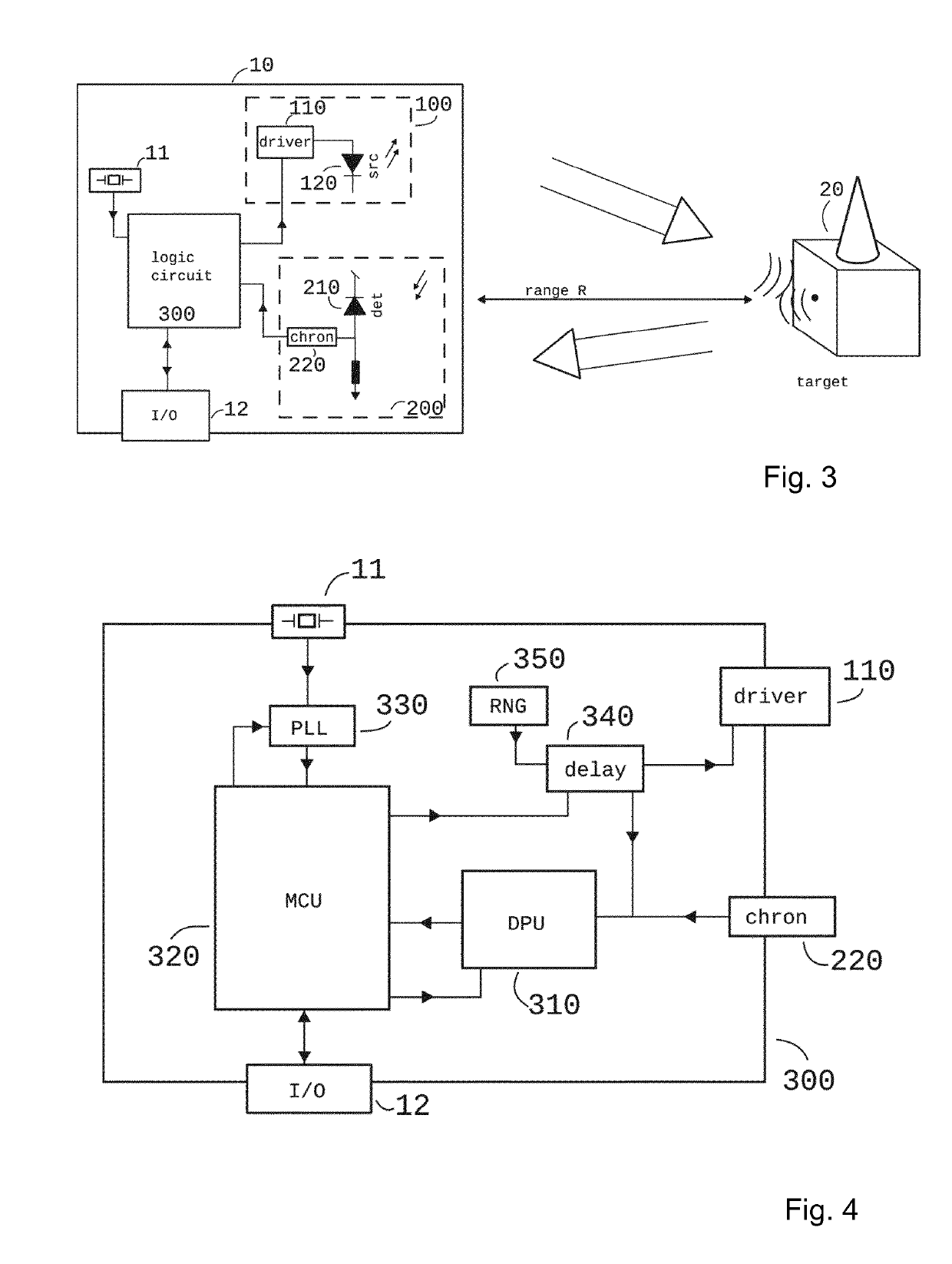
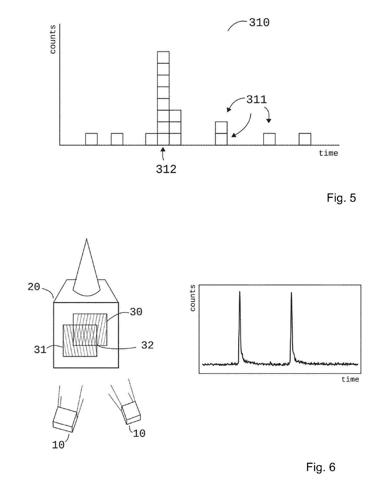
A method for measuring a distance to a target in a multi-user environment by means of at least one sensor, comprising: irradiating the environment by means of a series of radiation pulses, wherein series of radiation pulses are emitted at a determined repetition rate and with a determined random delay; collecting pulses that are reflected or scattered from the environment to at least a detector connected to at least one chronometer; assigning a timestamp at every detected pulse on the detector; subtracting the added delay from every registered timestamp coming from the chronometer, the result corresponding to the time of arrival; determining the statistical distribution of said time of arrival; determining the distance to the target from said statistical distribution.

Description

TECHNICAL FIELD[0001]The present invention relates to a method and a device for detecting distances by the means of sending out a signal into the observed environment and recording the time-of-flight (TOF) needed for said signal to bounce off a target and echo back. This sent out signal is typically a wave of acoustic and / or electro-magnetic nature. The first type (wave of acoustic nature) is usually called sonar (standing for SOund Navigation And Ranging) and typically using ultra-sound. The latter (wave of electro-magnetic nature) is called either radar (RAdio Detection And Ranging) or lidar (Light Detection And Ranging, sometimes also known as ladar standing for laser radar) depending on what electro-magnetic frequency range is employed.[0002]More specifically the present invention addresses the problem such time-of-flight systems encounter when multiple systems of similar construction are present in the same environment: these systems typically interfere with each other and end ...

Claims


Application Information

Patent Timeline
IPC IPC(8): G01S7/02G01S7/292G01S13/22G01S15/10G01S17/10
CPCG01S7/023G01S7/2923G01S13/222G01S15/105G01S17/10G01S7/2926G01S7/0235
Inventor KELLER, STEFAN THOMASCARRARA, LUCIO
Owner FASTREE3D
Learn More