
Eureka
For R&D, Eureka makes reading and utilizing patents & technical documents easy.
Eureka AIR
Designed for self-driven R&D workflows. Generate viable solutions, solve complex R&D challenges, empower your innovation with AI.

Eureka Materials
Designed for material experts only. Revolutionize your material R&D, from search, analyze, to developing new materials.

TechResearch
Generate reliable direction feasibility study reports for your R&D in just a few steps.

TechSeek
Discover and master advanced knowledge NOW. Basics, ideas, possibilities, all at once.

TechMind
As an expert in R&D Theories, TechMind can generates customized viable solutions instantly.

TechRisk
Analyze your overall solution with one click, know your potential R&D risks in advance.

TechMonitor
Get weekly tech updates, stay abreast of the latest tech innovations and key insights.
Roadside object recognition apparatus
- Summary
- Abstract
- Description
- Claims
- Application Information
AI Technical Summary
Benefits of technology
Problems solved by technology
Method used
Image

Examples
first embodiment
A. First Embodiment
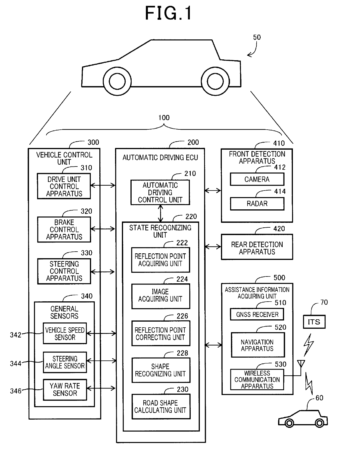
[0022]As shown in FIG. 1, a vehicle 50 according to a first embodiment includes an automatic driving control system 100 that corresponds to a vehicle control system. The automatic driving control system 100 includes an automatic driving electronic control unit (ECU) 200, a vehicle control unit 300, a front detection apparatus 410, a rear detection apparatus 420, and an assistance information acquiring unit 500. In the present description, the vehicle 50 is also referred to as an “own vehicle 50.”
[0023]The automatic driving ECU 200 is a circuit that includes a central processing unit (CPU) and a memory. The automatic driving ECU 200 actualizes the respective functions of an automatic driving control unit 210 and a state recognizing unit 220 by running a computer program that is stored in a non-volatile storage medium. A part of the functions of the automatic driving ECU 200 may be implemented by a hardware circuit.
[0024]The state recognizing unit 220 recognizes the...
second embodiment
B. Second Embodiment
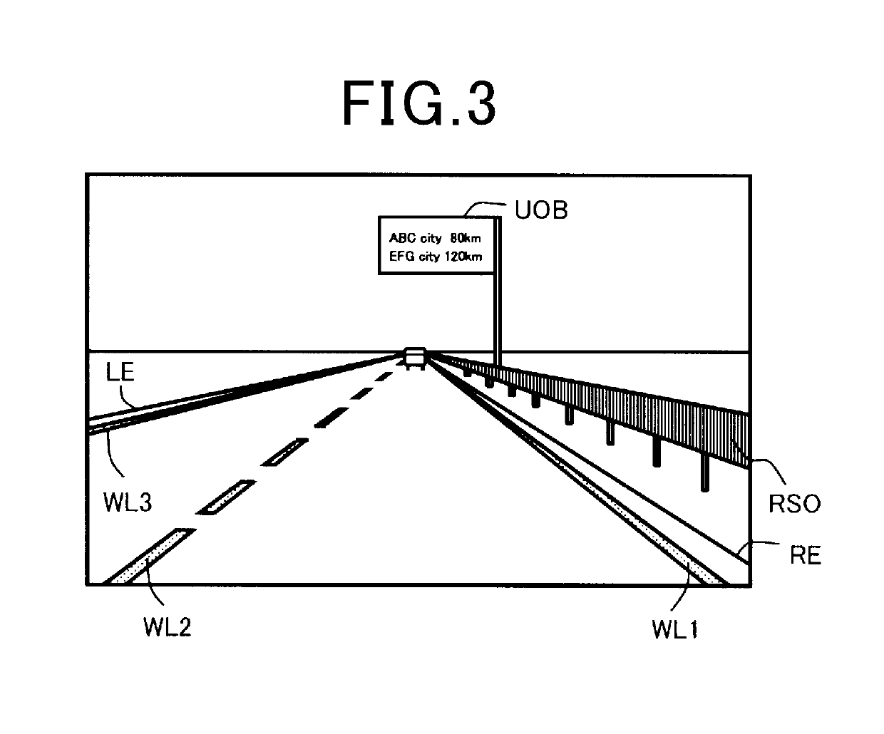
[0076]According to a second embodiment, when an object in an image captured by the camera 412 is recognized as being the overhead object UOB (FIG. 3) through image processing of the image, a process shown in FIG. 10, described below, is performed in addition to the above-described processes (FIG. 5 to FIG. 8) according to the first embodiment.
[0077]For example, the method for recognizing the overhead object UOB of the own vehicle 50 in an image includes pattern matching between the object in the image and numerous template images of overhead objects registered in advance. Alternatively, an object in the image can be recognized through use of artificial intelligence to which machine learning has been applied, and the object can be recognized as an overhead object should the object be present above the vanishing point in the image.
[0078]Moreover, when the GNSS signal cannot be detected, the likelihood of an overhead structure, such as an overpass or the ceiling of ...
third embodiment
C. Third Embodiment
[0084]According to a third embodiment, when an object in an image captured by the camera 412 is recognized as being the overhead object UOB (FIG. 3) through image processing the image, a process shown in FIG. 11, described below, is performed in addition to the above-described processes (FIG. 5 to FIG. 8) according to the first embodiment. In a manner similar to the process in FIG. 10, the process in FIG. 11, described hereafter, is a process in which an overhead object area UA2 in which the overhead object UOB is assumed to be present is set. The reflection points RPa, RP8, and RP9 present in the overhead object area UA2 are then removed from the reflection-point group. The third embodiment differs from the second embodiment in terms of the setting method of the overhead object area UA2.
[0085]As shown in FIG. 11, according to the third embodiment, the overhead object area UA2 is set as an area within a predetermined distance from the position at which the overhea...
PUM
 Abstract
Description
Claims
Application Information
 - R&D Engineer
- R&D Manager
- IP Professional
- Industry Leading Data Capabilities
- Powerful AI technology
- Patent DNA Extraction
Browse by: Latest US Patents, China's latest patents, Technical Efficacy Thesaurus, Application Domain, Technology Topic, Popular Technical Reports.
© 2024 PatSnap. All rights reserved.Legal|Privacy policy|Modern Slavery Act Transparency Statement|Sitemap|About US| Contact US: help@patsnap.com