Automatically actuated rear air drag reducing system and method of use thereof

a rear air drag and automatic actuation technology, which is applied in the direction of process and machine control, transportation and packaging, instruments, etc., can solve the problems of increasing engine power, significant air drag, turbulence and drag on the vehicle, etc., and achieves the effect of reducing aerodynamic drag, improving the aerodynamic quality of the trailer, and reducing aerodynamic drag

Active Publication Date: 2019-06-20
TRANSTEX LLC
View PDF0 Cites 11 Cited by
  • Summary
  • Abstract
  • Description
  • Claims
  • Application Information

AI Technical Summary

Benefits of technology

[0010]An aspect of our work, in accordance with at least one embodiment thereof, provides an automatically expandable and actuated aerodynamic air drag reducing apparatus adapted to be installed on a rear portion of the trailer to reduce the aerodynamic drag produced by the movement of the trailer when pulled by a vehicle.
[0011]An aspect of our work, in accordance with at least one embodiment thereof, provides an aerodynamic air drag reducing apparatus that is movable between a retracted configuration allowing access in t

Problems solved by technology

It is known that a significant amount of air drag is resulting when a vehicle travels on a road; this is due to an area of low pressure created at the rear end of the vehicle.
For example, with a tractor-trailer type vehicle, the air makes a sharp bend around the squared-off back of the trailer, thus causing turbulence and drag on the vehicle.
To overcome this problem, increased engine power is required and ther

Method used


Image

  • Automatically actuated rear air drag reducing system and method of use thereof
  • Automatically actuated rear air drag reducing system and method of use thereof
  • Automatically actuated rear air drag reducing system and method of use thereof

Examples


Embodiment Construction

[0099]A preferred embodiment of the present invention is described below with reference to the drawings.

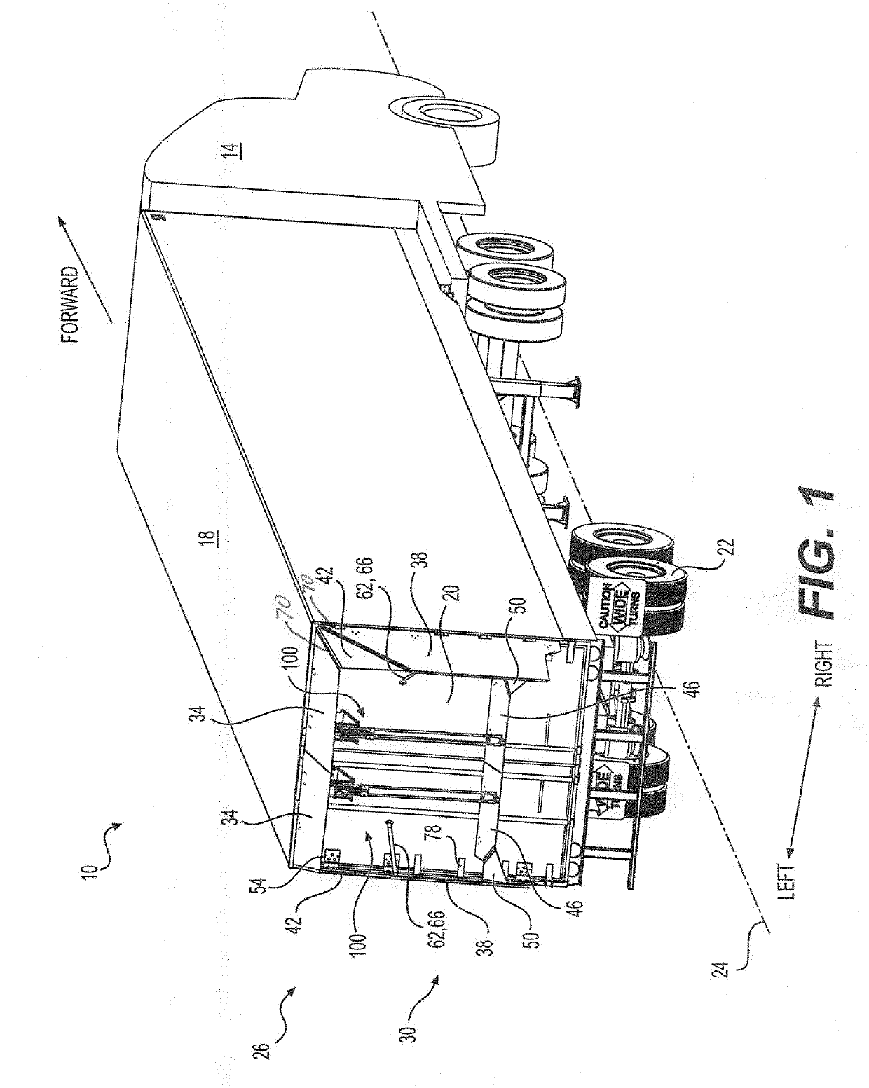
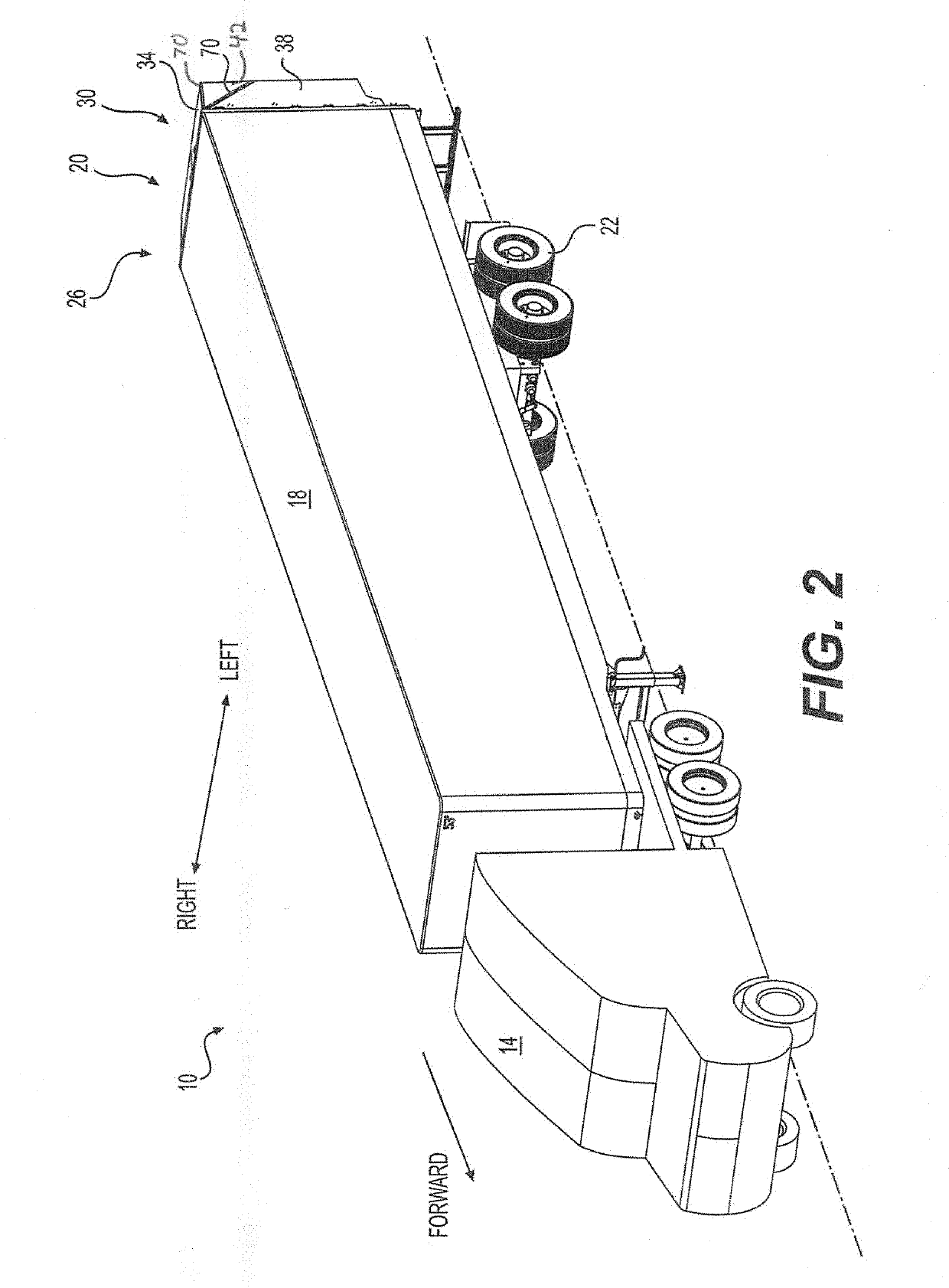
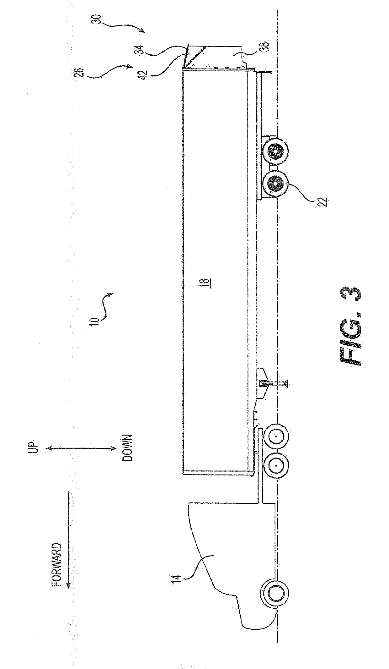
[0100]A vehicle 10 including a tractor 14 and a trailer 18 is illustrated in FIG. 1. The tractor 14 is operatively connected to the trailer 18 to pull the trailer 18 in a forward direction. The tractor 14 and the trailer 18 are equipped with a series of wheels 22 to propel and support the vehicle 10 with optional cargo therein. A tractor-trailer axis 24 is identified along a forward-rearward direction 24. The trailer 18 is equipped with a actuated aerodynamic air drag reducing apparatus 26 (hereinafter AAADRA 26) over a rear surface 20 of the trailer 18, as illustrated in its expanded configuration 30 in FIG. 1 throughout FIG. 4. In an embodiment, the AAADRA 26 is adapted to be expanded in an expanded configuration 30 and retractable in a retracted configuration 32, as illustrated in FIG. 6, on a basis of specific vehicle 10 speeds. The AAADRA 26 adapted to be expanded in the expa...


PUM


Abstract

This invention relates to an actuated aerodynamic air drag reducing apparatus for reducing the air drag of a vehicle, the actuated aerodynamic air drag reducing apparatus being adapted to move between an expanded configuration and a retracted configuration by an actuator on a basis of a signal associated to the behavior of the vehicle. The actuator being connected to a slider selectively connected to a pair of pivotable elongated members for being used between a plurality of configurations.

Description

CROSS-REFERENCE[0001]The present application relates to, claims priority from and is a non-provisional application of U.S. provisional application No. 62 / 608,192 filed Dec. 20, 2017 entitled REAR AIR DRAG REDUCING SYSTEM AND METHOD OF USE THEREOF, this document is incorporated herein by reference in its entirety.FIELD OF THE INVENTION[0002]This invention relates to an aerodynamic drag reducing apparatus adapted to be mounted on a rear portion of a trailer to improve the aerodynamic efficiency of the trailer. The present invention more precisely relates to an automatic vehicle expandable and retractable drag-reducing apparatus.BACKGROUND OF THE INVENTION[0003]Road tractors are generally used to pull trailers on roads to transport cargo. Aerodynamic apparatuses can be installed on the road tractor and / or on the trailer in order to reduce the aerodynamic air drag and improve fuel efficiency.[0004]Rear drag-reducing apparatuses are generally installed and secured to a rear portion of a ...

Claims


Application Information

Patent Timeline
IPC IPC(8): B62D35/00G05D3/00
CPCB62D35/001B62D35/007G05D3/00B62D63/08Y02T10/82
Inventor BOIVIN, MATHIEUDAOUST, SYLVAINDERNY, ALEXANDREJAVIER, ALFREDO
Owner TRANSTEX LLC
Why Eureka
Try Eureka