Dual-imaging vision system camera and method for using the same

a vision system and camera technology, applied in the field of machine vision systems, can solve the problems of short distances, sensors and optics configured to read at long distances may lack the required dof for such small codes, and achieve the effects of reducing the overall dimensions/volumetric footprint of the system, extending the reading range, and extending the focus rang

Active Publication Date: 2019-06-20
COGNEX CORP
View PDF1 Cites 12 Cited by
  • Summary
  • Abstract
  • Description
  • Claims
  • Application Information

AI Technical Summary

Benefits of technology

[0006]This invention overcomes disadvantages of the prior art by providing a vision system arrangement, typically having at least two imaging systems that enable a multi-function unit. The first imaging system, typically a standard, on-axis optical configuration can be used for long distances and larger feature sets (such as ID codes) and the second imaging system is typically an extended-depth of focus / field (DOF) configuration (such as the Scheimpflug configuration). This second imaging system allows reading of smaller feature sets (such as small ID codes, under (e.g.) 5MIL) and / or at short distances with an extended DOF. This arrangement can be used, for example, in combination with the standard imaging system to further extend the reading range of an overall (e.g.) ID-code-reading vison system. The optimization of such a vision system employs the standard imaging system for longer distances and larger codes, and the extended-DOF (Scheimpflug) imaging system for shorter distances and smaller codes. To further extend the DOF, the image sensor in the extended-DOF imaging system can be positioned with its longest dimension (in the case of a rectangular-shaped sensor) in the vertical axis (i.e. 90° from the standard configuration). Such a double-image sensor system can allow vision system processes to compute the distance from the vision system to the object to generate an autofocus setting for variable optics in the standard imaging system. The system can have an aimer to help the user to center the code in the desired axis. The aimer can be based on a structured light beam that projects a pattern onto the object surface in the region of the optical axis of the standard imaging system. The object is generally in focus if it is close to the horizontal plane containing the optical axis. By way of example, some exemplary aimer pattern shapes can include (but are not limited to) a laser beam (spot) coincident with the optical axis, a laser fan (line) coincident with the horizontal plane containing the optical axis, and two (e.g.) parallel, spaced-apart lines, in which one resides above and one below the horizontal plane containing the optical axis. If the object / region of interest resides between the two lines, its resulting image on the Scheimpflug sensor is in-focus.
[0007]Illustratively, a vision system, which can be employed in reading ID codes, provides extended reading range for large and small codes and includes two imaging systems. A fist, standard (on-axis) imaging system is provided, whose optical axis defines the full system optical axis and can have an aimer to guide the user to the center an ID code on this axis. This first standard imaging system is employed for medium and large distances and medium and larger codes. It can have an automatic focusing (autofocus) optics assembly, for example a variable (e.g. liquid) lens that is controlled by the vision system processor using distance data derived from the images and / or other external sensors. A second, extended-DOF imaging system is provided, based upon a tilted (e.g. Scheimpflug) configuration. This system can achieve extension of the focused range, and is employed for shorter distances and smaller codes. This second system is configured in such way that the object plane contains the standard imaging system optical axis. The DOF is defined by the image sensor size, so it can be configured in such way that the larger sensor dimension is used to further extend the DOF. To achieve this, the image sensor's longer axis is coplanar with the optics / lens optical axis and the first imaging system's optical axis. Depending on the distance of the code to the vision system, the code will appear in different positions along the vertical axis of the image sensor and its associated field of view. Calibrating this relationship into the vision system, the position of the code on the image is directly related to the code distance. This information can be used to compute the code size, and to optionally set the focus distance for the first imaging system.
[0008]In and illustrative embodiment, a vision system for imaging feature sets on an object surface, and associated method for the same, is provided. A first imaging system, having at least a first image sensor and first optics, defines a standard, on-axis configuration having a system optical axis. A second imaging system defines an extended-depth of focus (DOF) configuration with second optics. A vision system processor receives and processes image data from the first imaging system and the second imaging system. Illustratively, the feature sets comprise ID codes. The first imaging system is arranged to image at least one of medium distance, longer distance and larger ID codes and the second imaging system is arranged to image at least one of shorter distance and smaller ID codes. The second imaging system can be arranged according to a Scheimpflug (or equivalent, extended DOF) configuration. The second imaging system can also have a corresponding, second image sensor defining a plane that is oriented at a non-perpendicular angle with respect to an optical axis of the second optics, and an object plane of the second imaging system can be coincident with the system optical axis. The second optics can include a mirror assembly that redirects the optical axis of the second optics toward the system optical axis from an orientation that is tilted away from the system optical axis. Note that the mirror assembly is used (in this exemplary embodiment) to fold the optical path and reduce the overall dimensions / volumetric footprint of the system. The angle(s) of the mirror assembly has / have been defined in such way, that the second sensor is mounted approximately or substantially in the same plane as the first sensor (and, as such, both sensors can be mounted on the same circuit board). More generally, the second imaging system can have a mirror assembly that redirects a mounting location of the second image sensor to a location where a plane thereof is substantially parallel with a plane of the first image sensor.
[0009]Illustratively, the second image sensor can define a smaller-dimension axis and a larger-dimension axis, and the optical axis of the second optics can be coplanar with the system optical axis. The system can include an optical aimer on-axis with the system optical axis, and the aimer can be arranged to project a pattern that appears on the object surface as one of a spot adjacent to the optical axis, a line adjacent to the optical axis, and parallel, spaced apart lines on each of opposing sides of the optical axis. The aimer includes a light source that projects a structured light beam through a mirror assembly onto the system axis. The structured light beam can project a line onto the object surface oriented in a direction perpendicular to an optical axis of the first imaging system and an optical axis of the second imaging system. A measurement process, based on an image of the line acquired by the second imaging system, can then determine a height of the object surface and a distance to the object. The measurement process, based on an image acquired by the first imaging system, can also determine a length and a width of the object surface. Illustratively, the measurement process determines the length and the width based upon the distance to the object and a spacing between pixels in the image acquired by the first imaging system.
[0010]The mirror assembly can include a beam splitter that allows light to pass from the object surface to the first imaging system. More generally, the processor can be arranged to identify a location of features in an image of the second imaging system and thereby determine a distance of the vison system from the object surface containing the imaged features. A variable lens can be provided to the first optics and a control can set a focus of the variable lens based upon the distance. The variable lens can comprise a liquid lens. Illustratively, the second imaging system can define an optical axis that is tilted with respect to the system axis in a Scheimpflug configuration. The system can include a display, in which an image acquired by the first imaging system is projected on the display so as to assist in orienting the object surface with respect to the first imaging system. The display can include a graphic that represents a center thereof so that the object in the image can be aligned with the center

Problems solved by technology

It is often challenging to find and decode small-scale IDs—for example printed, peened or etched DataMatrix codes provided on parts—using either a fixed-mount ID reader or a handheld unit and at the same time preserve the capability to image larger IDs and / or at longer distances.
Thus, sensors and optics configured to read at longer distances may lack the needed DOF for such smaller codes and / or shorter distances.

Method used


Image

  • Dual-imaging vision system camera and method for using the same
  • Dual-imaging vision system camera and method for using the same
  • Dual-imaging vision system camera and method for using the same

Examples


Embodiment Construction

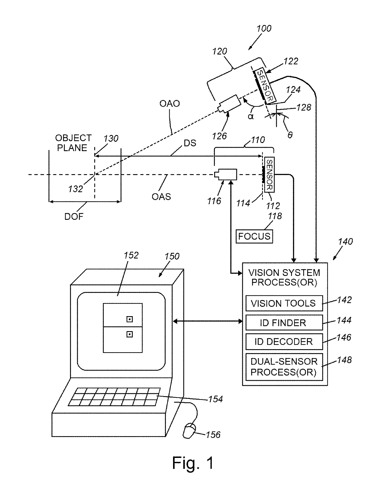
[0021]FIG. 1 shows a vision system arrangement 100 for use in providing an enhanced depth of field (DOF) useful in imaging small features, such as ID codes located on imaged object surfaces. The arrangement 100 includes a first imaging system (also herein termed a “camera assembly”) 110 arranged in accordance with a conventional, on-axis (straight-line) configuration with respect to the system optical axis OAS. The on-axis imaging system 110 includes an image sensor (also termed a “sensor” or “imager”) 112 defining an image plane 114 and an optics package 116, that can be any appropriate fixed or removable lens arrangement. This lens arrangement 116 can include a variable focus lens (for example an electronically controlled membrane liquid lens, such as those available from Optotune of Switzerland and Varioptic of France. In such arrangements, the liquid lens can be controlled using any appropriate focus data (for example, detecting sharpness with vision tools, use of range finders,...


PUM


Abstract

This invention provides a vision system, typically having at least two imaging systems/image sensors that enable a multi-function unit. The first imaging system, typically a standard, on-axis optical configuration can be used for long distances and larger feature sets and the second imaging system is typically an extended-depth of focus/field (DOF) configuration. This second imaging system allows reading of smaller feature sets/objects and/or at shorter distances. The reading range of an overall (e.g.) ID-code-reading vison system is extended and relatively small objects can be accurately imaged. The extended-DOF imaging system sensor can be positioned with its longest dimension in the vertical axis. The system can allow vision system processes to compute the distance from the vision system to the object to generate an autofocus setting for variable optics in the standard imaging system. An aimer can project structured light onto the object surface around the system optical axis.

Description

FIELD OF THE INVENTION[0001]This invention relates to machine vision systems for use in finding and decoding ID codes on objects, and more particularly to cameras for such vision systems.BACKGROUND OF THE INVENTION[0002]Vision systems that perform measurement, inspection, alignment of objects and / or decoding of symbology in the form of machine-readable symbols (also termed “IDs”, such as a 2D matrix symbol) are used in a wide range of applications and industries. These systems are based around the use of an image sensor, which acquires images (typically grayscale or color, and in one, two or three dimensions) of the subject or object, and processes these acquired images using an on-board or interconnected vision system processor. The processor generally includes both processing hardware and non-transitory computer-readable program instructions that perform one or more vision system processes to generate a desired output based upon the image's processed information. This image inform...

Claims


Application Information

Patent Timeline
Patent Type & Authority Applications(United States)
IPC IPC(8): G06K7/10G06K19/14H04N5/341
CPCG06K7/10386G06K19/14H04N5/3415G06K7/10722G06K7/10801G06K7/10831H04N25/41
Inventor LOZANO, ESTHER OTEONUNNINK, LAURENS
Owner COGNEX CORP
Why Eureka
Try Eureka