Power conversion device

a power semiconductor and switching device technology, applied in the direction of pulse technique, process and machine control, instruments, etc., can solve the problems of malfunction, reduced influence of switching noise increased power consumption of power semiconductor switching device, so as to and reduce the influence of switching nois

Active Publication Date: 2019-06-20
FUJI ELECTRIC CO LTD
View PDF1 Cites 3 Cited by
  • Summary
  • Abstract
  • Description
  • Claims
  • Application Information

AI Technical Summary

Benefits of technology

[0009]According to the above-described configuration, detection of the operating temperature of the power semiconductor switching device is not always performed, and is performed at timings according to the control signal received from the external control circuit. Since the operating temperature is detected at predetermined timings, for example, timings to turn off the power semiconductor switching device, as compared to the case of always detecting the operating temperature, the influence of switching noise of the power semiconductor switching device decreases. Therefore, it becomes possible to reduce the influence of switching noise of the power semiconductor switching device and change the amount of current to drive the power semiconductor switching device.
[0010]According to the above-described configuration, it becomes possible to reduce the influence of switching noise of the power semiconductor switching device and adjust the drive capability according the operating temperature of the power semiconductor switching device.

Problems solved by technology

However, this method has a problem that switching noise of the IGBT, for example, noise which is generated when the IGBT is turned on is likely to be superimposed on the voltage between both ends of the diode.
Therefore, in adjusting the drive capability according to the temperature of the IGBT, malfunction may occur due to the influence of noise.
Since the operating temperature is detected at predetermined timings, for example, timings to turn off the power semiconductor switching device, as compared to the case of always detecting the operating temperature, the influence of switching noise of the power semiconductor switching device decreases.

Method used


Image

  • Power conversion device
  • Power conversion device
  • Power conversion device

Examples


first embodiment

[0018](Configuration)

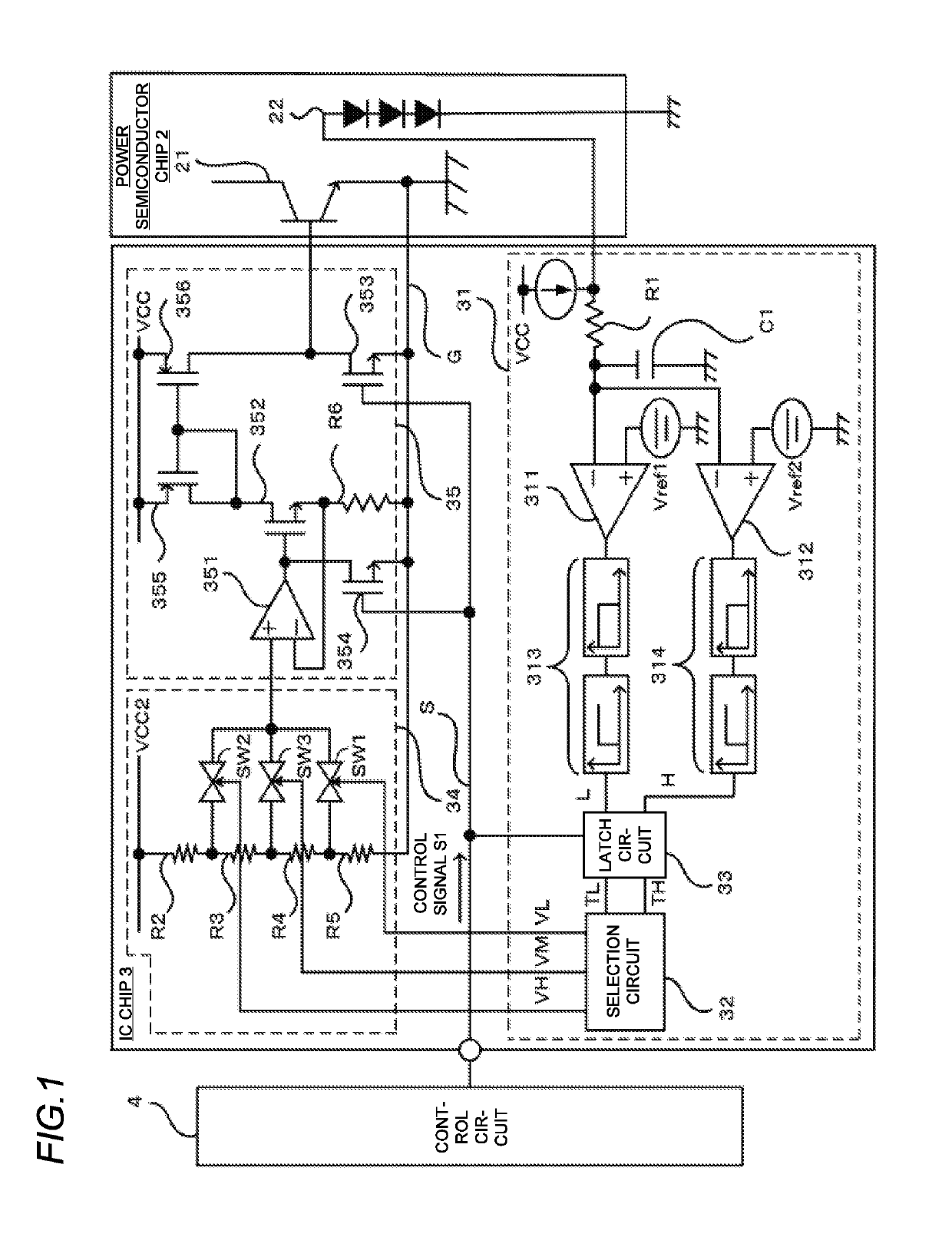
[0019]An IPM (Intelligent Power Module) 1 according to the present embodiment is a power conversion device applicable to, for example, joints of industrial robots, elevators, and air conditioners for business purposes, and is configured to include a power semiconductor chip 2 and an IC chip 3 as shown in FIG. 1.

[0020]The power semiconductor chip 2 is configured, for example, by forming an IGBT 21 and a plurality of diodes 22 in the same chip. The IGBT 21 is turned on according to a drive signal which is applied from the IC chip 3 to the gate, and supplies constant power to a load (not shown in the drawings) from the collector via the emitter. Also, the emitter of the IGBT 21 is connected to a ground line G of the IC chip 3 to be described below. The plurality of diodes 22 is formed in an area inside the power semiconductor chip 2 which is an area different from an area where the IGBT 21 is formed and is an appropriate area for detecting the temperature of the IG...

second embodiment

[0063]Now, a second embodiment will be described. In the first embodiment, the signal representing the operating temperature of the IGBT 21 is processed as a digital signal, for example, in the selection circuit 32 and the latch circuit 33. However, the present invention is not limited to this configuration, and it is also possible to use a circuit configuration for processing an analog signal representing the operating temperature of the IGBT 21. Hereinafter, the second embodiment using such a circuit configuration will be described. Components identical or similar to those of the first embodiment are denoted by the same reference symbols, and a detailed description thereof will not be made.

[0064](Configuration)

[0065]As shown in FIG. 4, a difference from the first embodiment is that the temperature detecting unit 31 of the IPM 1 includes an inverting amplifier 36 and an A / D converter 37 in place of the first and second comparators 311 and 312, the first and second filter circuits 3...


PUM


Abstract

A power conversion device includes a power semiconductor switching device and a drive circuit. The power semiconductor switching device is configured to supply constant power to a load by switching and to be turned on and off by a control signal from an external control circuit. The drive circuit is configured to detect an operating temperature of the power semiconductor switching device and drive the power semiconductor switching device according to a result of the detection. The drive circuit includes a temperature detecting unit configured to receive the control signal from the external control circuit and detect the operating temperature of the power semiconductor switching device at timings according to the control signal.

Description

CROSS-REFERENCE TO RELATED APPLICATIONS[0001]The present application claims priority from Japanese Patent Application No. 2017-242156, filed Dec. 18, 2017, the entire content of which is incorporated herein by reference.TECHNICAL FIELD[0002]The present invention relates to a power conversion device having a power semiconductor switching device, particularly, to a power conversion device that adjusts the drive capability of a power semiconductor switching device according to the operating temperature of the power semiconductor switching device.BACKGROUND ART[0003]An Intelligent Power Module (IPM) configured by forming a power semiconductor switching device such as an IGBT and a diode for temperature detection in the same chip is known. This main IPM detects the voltage between both ends of the diode, and detects the operating temperature of the IGBT in the same chip based on the magnitude of the voltage between both ends of the diode. Further, the IPM changes the amount of current to...

Claims


Application Information

Patent Timeline
Patent Type & Authority Applications(United States)
IPC IPC(8): H02M1/32H03K17/14H03K17/567H03K17/08H01L29/739H02M3/156
CPCH02M1/32H03K17/14H03K17/567H03K17/08H01L29/7393H02M3/156H02M2001/327H03K2017/0806H02M1/08H03K17/0826H02M1/327
Inventor NAKAMORI, AKIRA
Owner FUJI ELECTRIC CO LTD
Why Eureka
Try Eureka