Molded product conveying device

Active Publication Date: 2019-06-27
KIKUSUI SEISAKUSHO LTD
View PDF5 Cites 0 Cited by
  • Summary
  • Abstract
  • Description
  • Claims
  • Application Information

AI Technical Summary

Benefits of technology

[0011]At a delivery position set as a predetermined position on a rotation orbit of the pocket and the suction bore, where the molded product is received and sucked, the pocket is preliminarily fed with negative pressure, the suction bore is not fed with negative pressure, and the molded product is initially sucked to the pocket, and after the pocket and the suction bore pass the delivery position, the suction bore starts being fed with negative pressure and the molded product sucked to the pocket is sucked to the suction bore. This configuration further reduces variation in a relative position of the molded product to the suction bore, in comparison to a case where the molded product is directly sucked to the suction bore at the delivery position.
[0012]When the conveying device including the plurality of rotators disposed adjacent to each other to have the rotary axes in parallel with each other, the molded product can be conveyed a longer distance. In this case, the rotators each include a basal portion having a substantially circular disc shape when viewed along the rotary axis, and a flange expanding radially outward from an outer circumferential edge of the basal portion. The basal portion includes the pocket disposed at an outer circumference, and the flange includes the suction bore positioned to confront the pocket. At a delivery position set as a predetermined position on a rotation orbit of the pocket and the suction bore, where the molded product is delivered between the adjacent rotators, the basal portion of the first rotator and the basal portion of the second rotator are substantially flush with each other, the flange of the first rotator and the flange of the second rotator face each other along t

Problems solved by technology

Such a technique obviously causes gradual decrease in height of the molded products and thus requires disposition of a lift configured to halfway lift upward the molded products.
Furthermore, the molded products fall onto chutes repeatedly and may thus hit an inner wall or a bottom wall of the chute or collide with each other to be damaged by being broken, chipped, abraded, or the like.
In particular, molded products having less hardness such as orally disintegrating tablets (i.e., OD tablets that disintegrate with saliva or a small amount of water in an oral cavity) o

Method used


Image

  • Molded product conveying device
  • Molded product conveying device
  • Molded product conveying device

Examples


Example

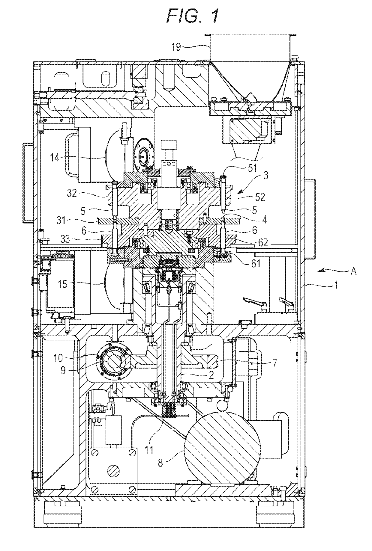
[0031]An exemplary embodiment of the exemplary invention will now be described with reference to the drawings. Initially described is an overview of an entire rotary compression-molding machine (hereinafter, referred to as the “molding machine”) A according to the exemplary embodiment. The molding machine A is configured to compress a powdery material to obtain a compression molded product P such as a pharmaceutical tablet. A powdery material is an aggregate of minute solids and conceptually includes an aggregate of particles such as so-called granules and an aggregate of powder smaller than such particles. As shown exemplarily in FIG. 1, the molding machine A includes a frame 1 accommodating an upright shaft 2 functioning as a rotary shaft and a turret 3 attached to a connection portion that is disposed at a top of the upright shaft 2.

[0032]The turret 3 horizontally rotates about the upright shaft 2, and more specifically, spins. The turret 3 includes a die table (e.g., die disc) 3...


PUM


Abstract

A molded product conveying device configures to suck a molded product to a rotator rotating about a predetermined rotary axis and to convey the molded product along a rotation orbit. The conveying device includes a pocket disposed along an outer circumference of the rotator, recessed inward and opened outward radially and perpendicularly to the rotary axis, and fed therein with negative pressure to suck the molded product, and a suction bore positioned to confront the pocket at a first end or a second end along the rotary axis of the rotator, opened toward the pocket to be at least partially overlapped with the pocket when viewed along the rotary axis, and fed therein with a negative pressure to suck the molded product.

Description

BACKGROUND[0001]There has been known a rotary compression-molding machine including a die table of a turret having die bores, an upper punch and a lower punch slidably retained above and below each of the die bores, and configured to horizontally rotate the die table and the punches together to compression mold (or to make tablet) a powdery material filled in the die bores when the paired upper and lower punches pass between an upper roll and a lower roll. The molding machine of this type is applied, for example, to produce pharmaceutical tablets, food products, electronic components, and the like.[0002]Each molded product is subjected to various post processes. Examples of the post processes include inspecting the molded product as to whether or not the molded product has a defective exterior, removing dust adhering to the molded product, inspecting the molded product in terms of volume, weight, or components, inspecting as to whether or not the molded product contains any alien me...

Claims


Application Information

Patent Timeline
IPC IPC(8): B65G47/91B30B15/32B30B11/08
CPCB65G47/91B30B15/32B30B11/08B65G47/848B30B11/005B65G29/00B65G47/915B65G2201/027
Inventor KAKITANI, TOMOHIRO
Owner KIKUSUI SEISAKUSHO LTD
Why Eureka
Try Eureka