
Variable stiffness bearing suspension device

Active Publication Date: 2019-06-27
SN DETUDE & DE CONSTR DE MOTEURS DAVIATION S N E C M A
View PDF12 Cites 3 Cited by
  • Summary
  • Abstract
  • Description
  • Claims
  • Application Information

AI Technical Summary

Benefits of technology

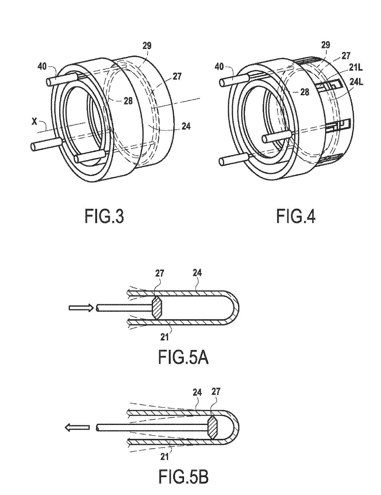
The bearing suspension device described in this patent makes it possible to change the stiffness of the device in response to the force transmitted between two points. By moving the thrust points in the axial direction, the length of the cantilever between the two points can be adjusted, which changes the stiffness of the device. This allows for a wider range of stiffness values to be achieved without taking up too much space. The device can be designed to provide radial contact all around its perimeter. The method described in the patent involves adjusting the axial length of the cantilevers by moving the thrust points and adjusting the stiffness of the device accordingly.

Problems solved by technology

Manufacturing imperfections and other parasitic effects can generate unbalances and thus radial vibration acting on the bearings.
Nevertheless, those disclosed devices are limited to only two alternative radial stiffnesses.

Method used


Image

  • Variable stiffness bearing suspension device
  • Variable stiffness bearing suspension device

Examples


Embodiment Construction

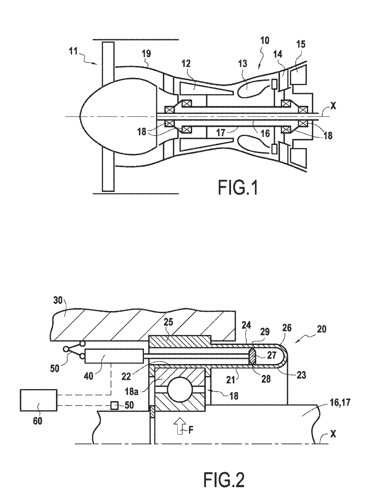
[0017]FIG. 1 is a diagram showing a turbomachine 10 that is suitable for including a bearing suspension device in accordance with the present disclosure. In this context, the term “turbomachine” is used to designate any machine in which energy can be transferred between a fluid flow and at least one set of blades, such as for example a compressor, a pump, a turbine, a propeller, or indeed a combination of at least two of these, and in particular a gas turbine engine. In the example shown, the turbomachine 10 is such a gas turbine engine, more specifically a bypass turbojet or “turbofan” that comprises a fan 11, a compressor 12, a combustion chamber 13, a first turbine 14, and a second turbine 15 that are arranged in succession in the direction M that air and combustion gas flow through. The bearing suspension device of the present invention can nevertheless also be applied to other types of gas turbine engine, such as turbojets, turboprops, turboshaft engines, and other types of tur...


PUM


Abstract

A bearing suspension device includes first and second elastically flexible members extending in an axial direction; and first and second thrust points that are movable in the axial direction and that are in radial contact respectively with the first and second elastically flexible members. The bearing suspension device is configured to transmit a radial force by the first elastically flexible member bending between the first thrust point and a first end of the first elastically flexible member, and also to transmit the radial force by the second elastically flexible member bending between the second thrust point and a first end of the second elastically flexible member.

Description

BACKGROUND OF THE INVENTION[0001]The present disclosure relates to a bearing suspension device, and more particularly to a bearing suspension device of variable radial stiffness.[0002]In a rotary machine, a rotary shaft is typically supported by one or more bearings, which, by way of non-exclusive example, may be rolling bearings, oil bearings, or gas bearings. The lifetime of such bearings is strongly dependent on the vibratory characteristics of the rotary machine. Manufacturing imperfections and other parasitic effects can generate unbalances and thus radial vibration acting on the bearings. It is therefore common practice to use devices for absorbing such vibration, at least in part. Thus, in the specification of French patent application published under the No. FR 3 013 760 A1, a device is disclosed that comprises a flexible cage arranged between an outer ring of the bearing and a support for the bearing.[0003]Nevertheless, in such a rotary machine, and in particular in a rotar...

Claims


Application Information

Patent Timeline
IPC IPC(8): F01D25/16F02C7/06
CPCF01D25/164F02C7/06F16C27/066F16C25/06F05D2240/50F05D2260/96F16C2360/23F16C35/077F16C19/26F16C19/522F16C19/527F16C27/04F16C27/045F16C2233/00F16C33/586F16F15/06
Inventor BENSLAMA, YANISBENYAMIN, SERGETAN-KIM, ALEXANDRE JEAN-MARIE
Owner SN DETUDE & DE CONSTR DE MOTEURS DAVIATION S N E C M A
Learn More