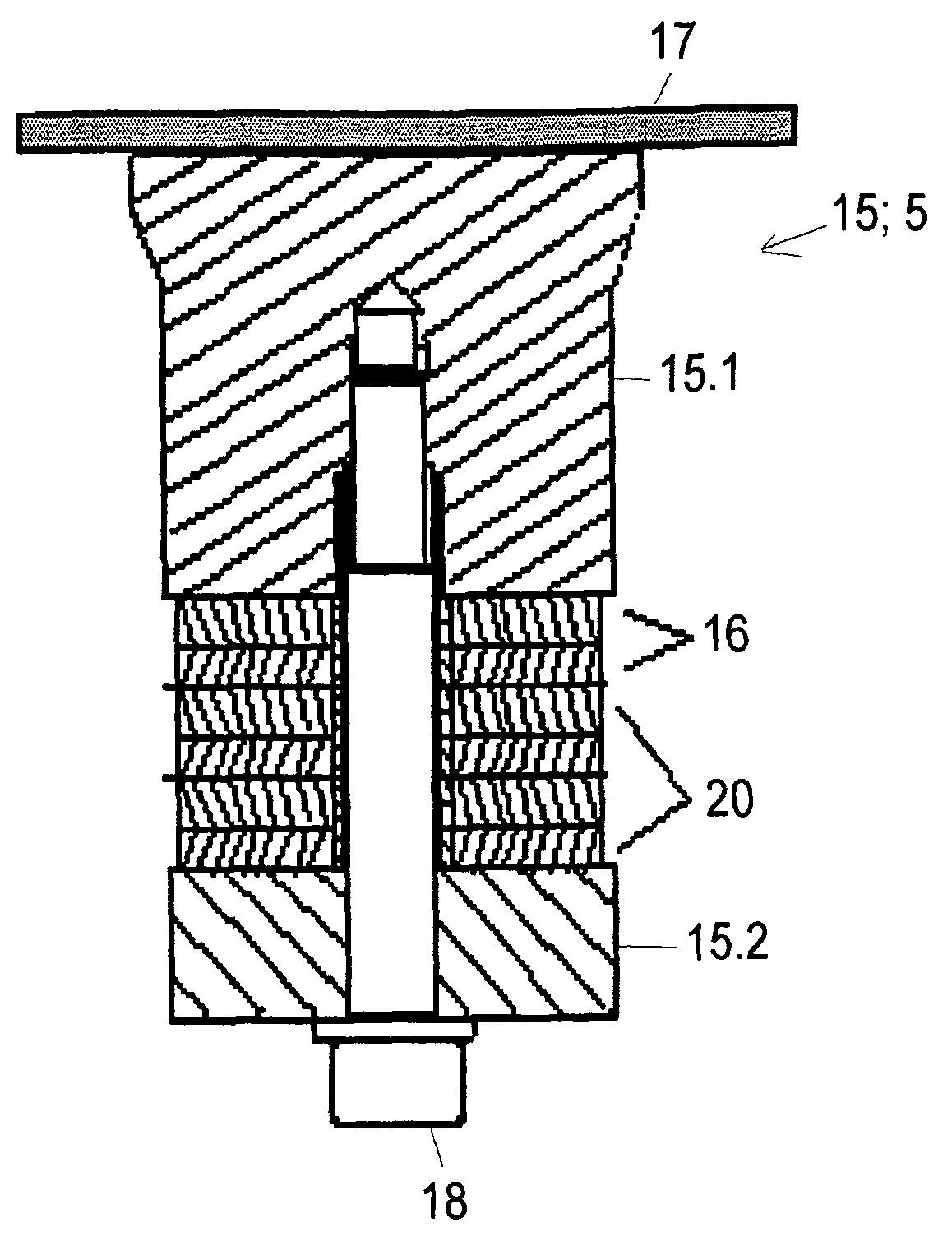
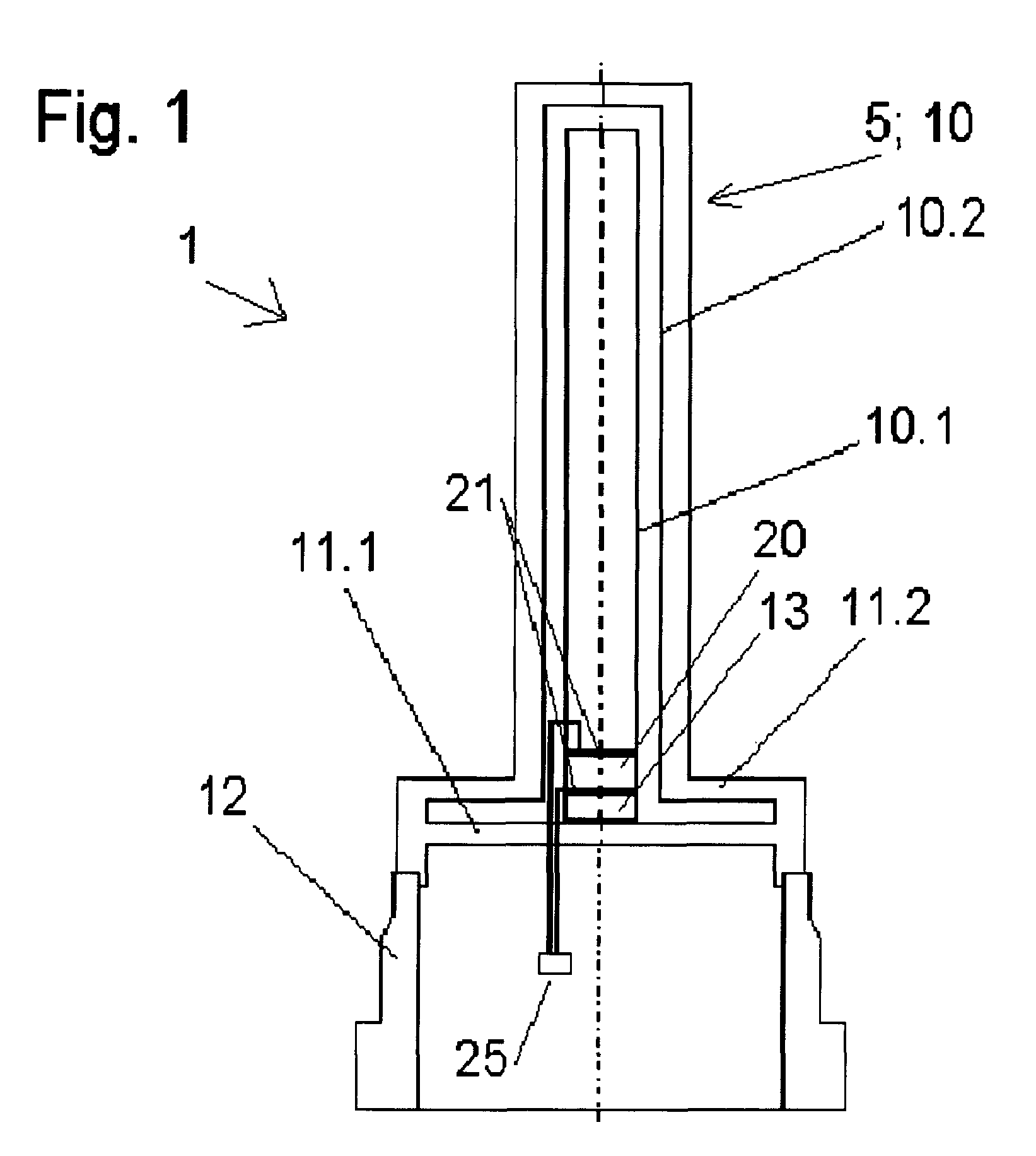
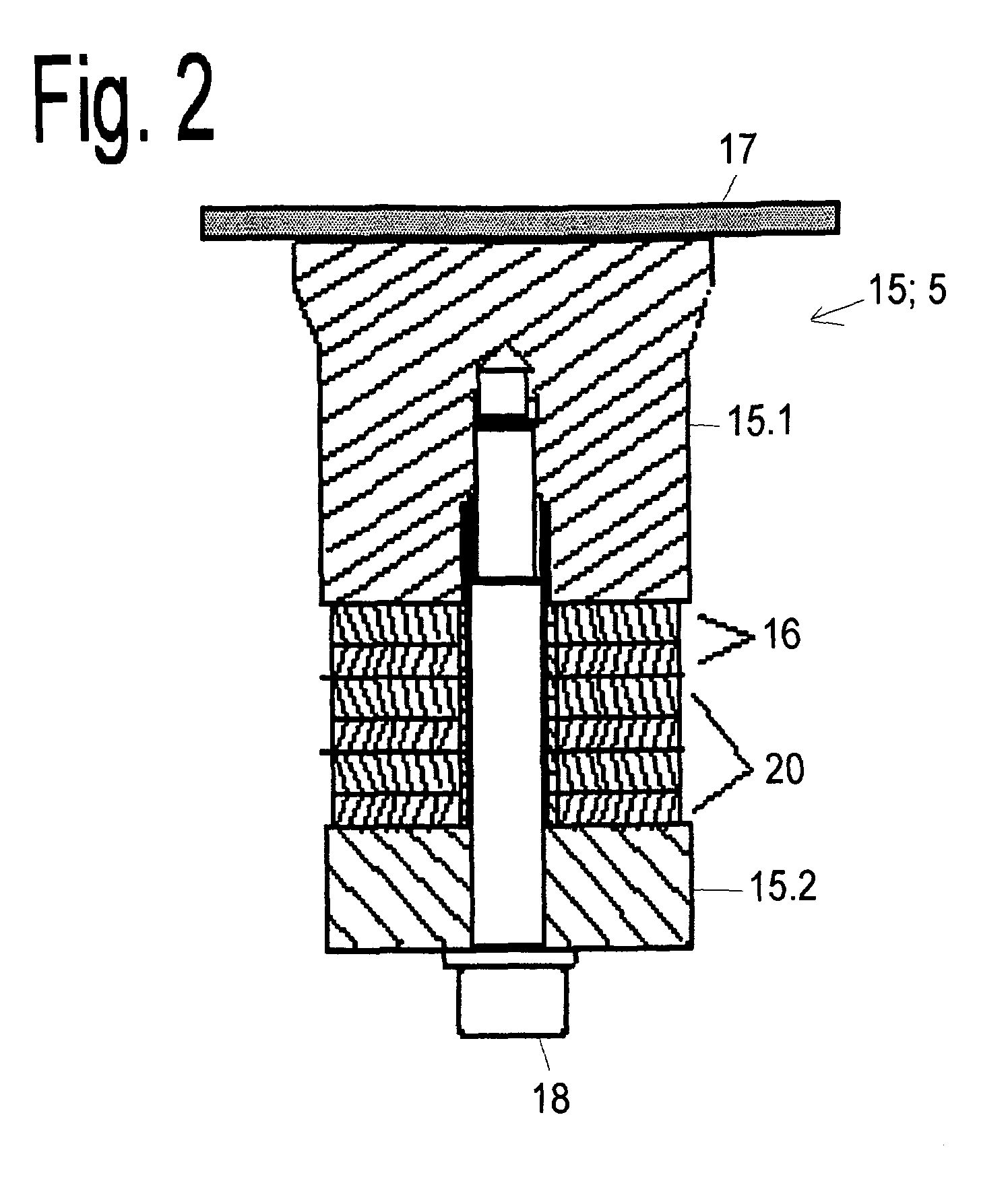
[0018]One embodiment for the area of ultrasonic oscillations includes that: At least one front-side
mass and one rear-side
mass are provided in the oscillatable unit; at least one sending / receiving piezo is provided between the two masses; at least one tuning unit is a component of one of the two masses; and the
resonance frequency of the oscillatable unit lies in the ultrasonic range. The oscillatable unit is in this second embodiment, thus, an ultrasonic
transducer or
ultrasonic sensor of the Langevin-type. The
resonance frequency is, in such case, usually inversely proportional to the length of the total unit formed of the 2 masses and the sending / receiving piezo, since the
half wave length corresponds to this length. This condition can, however, be changed by changing the velocity of sound in at least one of the two masses, and it is here that also the great
advantage of the invention is achieved. If at least one tuning unit is a component of at least one mass, then, by changing the stiffness, also the velocity of sound in this mass can be changed. In this way, a much easier matching of the resonance frequency is possible as compared e.g. to a shortening or lengthening of the masses. This tuning unit is, therefore, especially relevant for being able to react to manufacturing tolerances. Furthermore, in this way, the sensor can also be tuned to a desired frequency range without having to use an, otherwise, usual
damper, which most often leads to a reduction of the power since it makes the sensor broadbanded. It is also possible, in this way, that the ultrasonic
transducer is tunable with full power at a plurality of resonance frequencies. The invention is, however, also in this area, not limited to the application in the ultrasonic range.
[0019]An advantageous embodiment provides that at least one matching layer is provided in the oscillatable unit for
coupling to the medium. In order to assure maximum effectiveness in certain media (e.g. water), a λ / 4 matching layer is often used. Such matching
layers have, however, usually another temperature dependence of the velocity of sound as compared to the piezo
resonator. Therefore, at certain temperatures the power drops. With the tuning unit of the invention, it is possible to provide a matching of the resonance frequency to the λ / 4 matching layer for a wide temperature range. The resonance frequency can, thus, be matched to the matching layer upon temperature changes via the tuning unit of the invention.
[0020]An advantageous embodiment includes that at least one bolt is provided in the oscillatable unit for producing a prestress. The connection between the two masses and the sending / receiving piezo can be accomplished by adhesives or by a bolt. The power of the
ultrasonic sensor depends on the mechanical prestress between the parts. This prestress is defined via the bolt. If the bolt is loosened, the prestress goes down and also the power. In the sense of
predictive maintenance, there is the question of how this prestress can be checked without having to unscrew the unit. Such a capability would allow timely recognition of loss of the prestress without having to remove the measuring apparatus from the installed state. The invention makes possible thus a direct checking in the field. When the
ultrasonic sensor is made of different components of different stiffness, then usually the smallest occurring stiffness is dominant. With the tuning unit of the invention, however, it is possible to vary the stiffness without changing the prestress. By this change, a certain influence on the resonance frequency of the structure results provided that the sensor itself does not deviate too much from the stiffness of the tuning unit. If the mechanical prestress is reduced, then, however, also the frequency change by the changing of the stiffness is reduced, because the total stiffness is defined more strongly by the loosened bolt. In this way, it is possible to deduce, from the deviating from the known frequency change, that the bolt has loosened.
[0021]An embodiment of the apparatus of the invention provides that the oscillatable unit includes at least one measuring tube of a measurement
pickup of vibration-type inserted into the course of a pipeline, especially a Coriolis mass flow or a Coriolis mass flow / density meter. Such principles of measurement are disclosed in the documents U.S. Pat. No. 5,796,011, U.S. Pat. No. 6,651,513, U.S. Pat. No. 6,006,609 or U.S. Pat. No. 5,531,126.
[0022]The object of the invention relates also to a method for changing the resonance frequency of an apparatus for determining and / or monitoring at least one physical or chemical, process variable of a medium with at least one oscillatable unit, which produces and / or receives mechanical oscillations. The term “resonance frequency of an apparatus” means, in such case, the resonance, or, in general, the oscillation, frequency with which the measuring apparatus works, thus determines and / or measures, the corresponding process variable.
[0023]The object is achieved with reference to the method of the invention by changing the stiffness of at least one tuning unit, which is connected with the oscillatable unit or is a component of the oscillatable unit. If the oscillatable unit is an oscillatable
system whose resonance frequency is determined by the stiffness of at least one component, then for example, a piezoelectric unit enables a simple and above all electrically controllable tuning of the resonance frequency. Additionally, the embodiments for the above described apparatus of the invention can also be applied for the method.


