Instrumented flow passage of a turbine engine

a turbine engine and instrument technology, applied in the direction of instruments, machines/engines, lighting and heating apparatus, etc., can solve the problems of high risk of resonance, damage to components of the turbine engine arranged downstream, and damage caused by such dislocations to be particularly severe, so as to achieve simple, efficient and cost-effective effects

Active Publication Date: 2017-06-01
SN DETUDE & DE CONSTR DE MOTEURS DAVIATION S N E C M A
View PDF13 Cites 3 Cited by
  • Summary
  • Abstract
  • Description
  • Claims
  • Application Information

AI Technical Summary

Benefits of technology

[0020]Hence, when the measuring element comprising means of instrumentation is subjected to vibrations close to its resonance frequency, it is possible, via the supply with pressurized fluid, to vary the stiffness K of the element by varying the fluid pressure inside the tubular cavity of the element. Changing the stiffness K (N·m−1) of the element causes a change in the natural frequency of the measuring element, which allows distancing of its vibration frequency from its resonance frequency during operation.
[0031]The cavities formed in the branches of the U are supplied with pressurized fluid, thereby making it possible to vary if necessary the stiffness of each of the branches.
[0038]The means of control make it possible to send a setpoint pressure value to the means of supply, wherein said means of supply are configured to be able to adapt the pressurized fluid supply to the setpoint value.
[0047]The method according to the invention allows, using means of modification of the pressure in a cavity of the measuring element, modification of the natural frequency fr1 of the element such that this frequency is sufficiently distanced from the vibration frequency f1 depending on the element. It is thus possible to limit the risks of resonance of the element.

Problems solved by technology

The debris thus released circulates in the flow passage and may damage components of the turbine engine arranged downstream.
It is clear that the damage caused by such dislocation may be particularly severe when a measuring element 42a, 42b, 42c is installed in the primary flow passage, since the debris pay damage the combustion chamber and the fixed and rotating components of the high-pressure and low-pressure turbines.
A first source of vibration results for example from the residual imbalance of the rotating assemblies, i.e. of the low-pressure and high-pressure rotors.
If the first normal mode of the measuring element is close to 1000 Hz, the element will have a high risk of resonating in this case.
When the vibration frequency of the element f1 comes close to its resonance frequency fr1 of rank 1 or its harmonic natural frequencies, there is a high risk of resonance of the measuring element, which increases the risk of crack formation.
In other words, some ranges of operating speeds of the turbofan may be prohibited in the presence of the measuring element, thereby reducing the value of the engine trials.
Stoppage of the test turbine engine may therefore be necessary in order to change the element, which results in an increase in costs.

Method used


Image

  • Instrumented flow passage of a turbine engine
  • Instrumented flow passage of a turbine engine
  • Instrumented flow passage of a turbine engine

Examples


Embodiment Construction

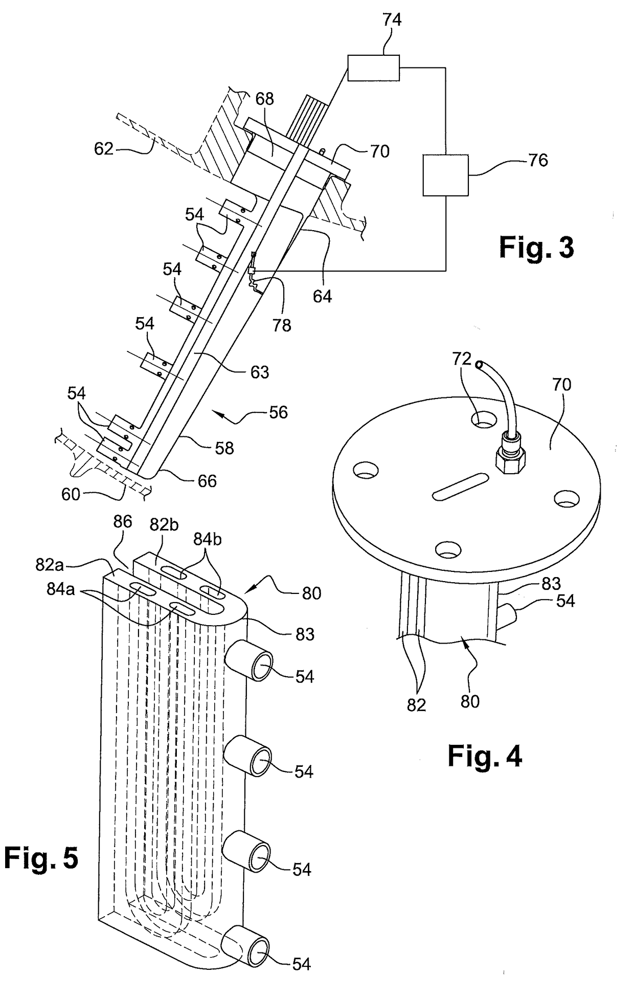
[0060]FIG. 3 represents a portion of a turbine engine annular flow passage such as an annular secondary air flow passage, comprising a measurement device 56 for measuring characteristics of the air flow featuring a measuring element 58 extending in the air flow between internal 60 and external 62 revolution walls delimiting the air flow.

[0061]The measuring element 58 comprises a first radially external end 64 and a second end 66, radially internal. The radially external end is connected to a cylindrical portion 68 interdependent with a disc-shaped base 70 perforated by four holes 72 (FIGS. 3 and 6). The measuring element 58 is inserted radially from outside the radially external wall 62 into an opening in the latter such that the cylindrical portion 68 and the disc 70 engage in recesses of matching shape formed in the thickness of the external wall 62. Fixing screws are subsequently inserted into the holes 72 in the base 70 and into the holes opposite in the external wall 62. The fi...


PUM


Abstract

An annular air flow passage, particularly for a turbine engine, comprising two radially internal and external annular walls. A measuring element is elongated in a direction between the internal and external annular walls, and a first of the internal or external ends of the element is fixed rigidly to a first of the internal or external walls. The element includes at least one tubular cavity extending along the element and supplied with pressurized fluid.

Description

BACKGROUND OF THE INVENTION[0001]1. Field of the Invention[0002]The present invention concerns an annular air flow passage, particularly for a turbine engine, such as a turbofan or turboprop, comprising an elongated element passing through the flow passage and capable of being instrumented.[0003]2. Description of the Related Art[0004]Conventionally, a dual-flow turbofan 10, as illustrated in FIG. 1, consists of a gas turbine 12 with a revolution axis 14 driving a ducted fan wheel 16, wherein the latter is generally positioned upstream from the turbofan. The mass of air sucked in by the engine is divided into a primary air flow (arrow A) that flows through the gas turbine 12 or engine core and a secondary air flow (arrow B) originating from the fan 16 and surrounding the engine core, wherein the primary and secondary air flows are concentric and circulate in a primary annular flow passage 18 and a secondary annular flow passage 20 respectively 8.[0005]In a manner well known per se, t...

Claims


Application Information

Patent Timeline
Patent Type & Authority Applications(United States)
IPC IPC(8): F01D21/00F01D11/00G01H13/00F01D9/02
CPCF01D21/003F01D9/02F05D2270/334G01H13/00F05D2220/30F01D11/003F16F15/0275G01M9/065F01D9/065F01D17/08Y02T50/60F01D5/10F01D17/02F23R3/02
Inventor GIORDAN, JEREMYBADER, VALENTINE LUCETTELEROUX, ANDRE PIERRE JEAN XAVIERROUSSELIN, STEPHANE
Owner SN DETUDE & DE CONSTR DE MOTEURS DAVIATION S N E C M A
Why Eureka
Try Eureka