Active vibration controller

a technology of active vibration and controller, which is applied in the direction of mechanical equipment, process and machine control, instruments, etc., can solve the problems of insufficient damping effect, inability to fully give the damping effect of the dynamic absorber, and direct application of outer energy, so as to reduce the stiffness of the magnetic viscoelastic elastomer, and reduce the manufacturing cost

Active Publication Date: 2020-04-21
HONDA MOTOR CO LTD
View PDF10 Cites 3 Cited by
  • Summary
  • Abstract
  • Description
  • Claims
  • Application Information

AI Technical Summary

Benefits of technology

[0004]On the other hand, as a counter part of the passive type of damping device, an active mass damper is known. In this method, an actuator for forcibly vibrating a mass is installed in addition to the mass element. This provides a high damping effect irrespective of stable or unstable in frequency because, theoretically, an arbitrary damping force can be generated though any disturbance is applied. However, there are problems in that a device to directly apply outer energy becomes complicated, that a control system designing become necessary to avoid unstableness, and that a cost is high. Further, there is a semi-active type of a control method which is intermediate type between the passive type and the active type. In the semi-active type of damper, a physical characteristic of one of configuration elements, which is originally fixed in the passive type system, is made variable with some means to have variability in the physical characteristic in the system. This enables the system control while the variation due to a disturbance is tracked to some extent. The semi-active type of control method has advantageous effects such as a control performance close to the active type of control method with reliability and stability derived from the passive elements and provides a device at a cost which is lower than that of the active type of control.
[0005]WO 2012 / 026332 disclosed a configuration for varying an elastic modulus of a magnetic elastic body by application of a magnetic field generated by an exciting coil using a configuration in which the exciting coil is arranged around an outer circumference of a magnetic elastic body of which elastic modulus can be changed by application of a magnetic field by the exciting coil.
[0006]In WO 2012 / 026332, it is disclosed that a stiffness of a magnetic viscoelastic elastomer is changed by application of a magnetic field to the magnetic response-type elastic body (magnetic viscoelastic elastomer) is changed. When the magnetic field is applied to the magnetic viscoelastic elastomer, the magnetic field is applied to the magnetic viscoelastic elastomer uniformly and varies the stiffness of the magnetic viscoelastic elastomer in accordance with the application quantity of the magnetic field.
[0007]However, in the technology disclosed in WO 2012 / 026332, it was forced to distribute magnetic powder to a part which does not largely contribute to change the stiffness of the magnetic viscoelastic elastomer. This results in increase in a lower limit of a base stiffness of the magnetic viscoelastic elastomer because a larger amount of the magnetic powder must be distributed to the part that does not contribute to variation in the stiffness, which may result in increase in the lower limit of the stiffness of the magnetic viscoelastic elastomer and increase in the manufacturing cost. Further, the magnetic field cannot be applied to the magnetic viscoelastic elastomer efficiently because the magnetic field may be applied to the part of the magnetic viscoelastic elastomer in which the magnetic powder is not distributed. Accordingly, it was not performed to apply the magnetic field to the magnetic viscoelastic elastomer efficiently.SUMMARY OF THE INVENTION
[0008]An aspect of the present invention provides arrangement of the magnetic powder in the concentrated manner in a part which largely contributes to vary the stiffness of the magnetic viscoelastic elastomer, and the magnetic field is in the concentrated manner applied to the part in which the magnetic powder is in the concentrated manner arranged.
[0009]Accordingly, it may be required to apply the magnetic field in the concentrated manner to the target part of the magnetic viscoelastic elastomer.

Problems solved by technology

However, when the frequency of the disturbance vibration is different from the eigenfrequency even slightly or when the frequency of the disturbance vibration varies as time passes, i.e., in an unstable state, the damper effect of the dynamic absorber cannot be fully given.
However, its damping effect is insufficient.
However, there are problems in that a device to directly apply outer energy becomes complicated, that a control system designing become necessary to avoid unstableness, and that a cost is high.
However, in the technology disclosed in WO 2012 / 026332, it was forced to distribute magnetic powder to a part which does not largely contribute to change the stiffness of the magnetic viscoelastic elastomer.
This results in increase in a lower limit of a base stiffness of the magnetic viscoelastic elastomer because a larger amount of the magnetic powder must be distributed to the part that does not contribute to variation in the stiffness, which may result in increase in the lower limit of the stiffness of the magnetic viscoelastic elastomer and increase in the manufacturing cost.
Further, the magnetic field cannot be applied to the magnetic viscoelastic elastomer efficiently because the magnetic field may be applied to the part of the magnetic viscoelastic elastomer in which the magnetic powder is not distributed.
Accordingly, it was not performed to apply the magnetic field to the magnetic viscoelastic elastomer efficiently.

Method used


Image

  • Active vibration controller
  • Active vibration controller
  • Active vibration controller

Examples


first embodiment

[0048]A first embodiment of the present invention is described below in detail, referring to the attached drawing.

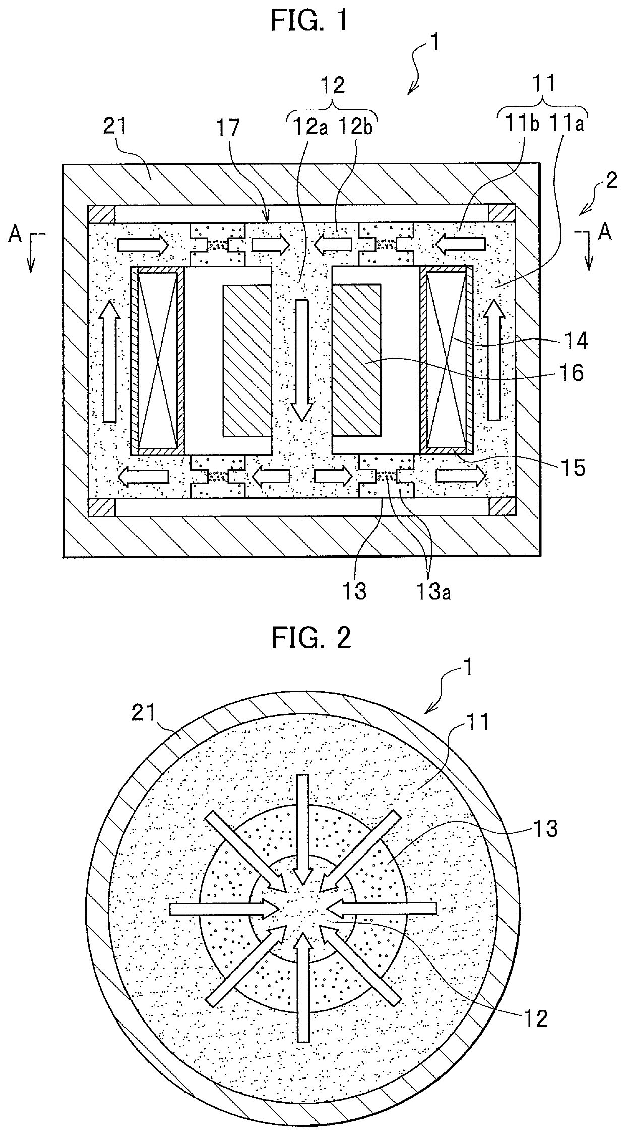
[0049]FIG. 1 is an elevational sectional view of the active vibration controller according to the first embodiment of the present invention, and FIG. 2 is a sectional view of the active vibration controller, taken along a line A-A in FIG. 1.

[0050]An active vibration controller 1 includes a housing 21 having a non-magnetic hollow circular cylinder. The housing 21 houses a movable part 17 which can move in response to an input force from the outside and a first magnetic core 11. The movable part 17, disposed inside the first magnetic core 11, includes a second magnetic core 12 and an adjusting mass 16. Further, the housing 21 houses an exciting coil 14 for generating a magnetic field having intensity according to the current supplied thereto. The exciting coil 14 is made by winding a wire around a bobbin 15 having an annular shape.

[0051]The first magnetic core (first magne...

second embodiment

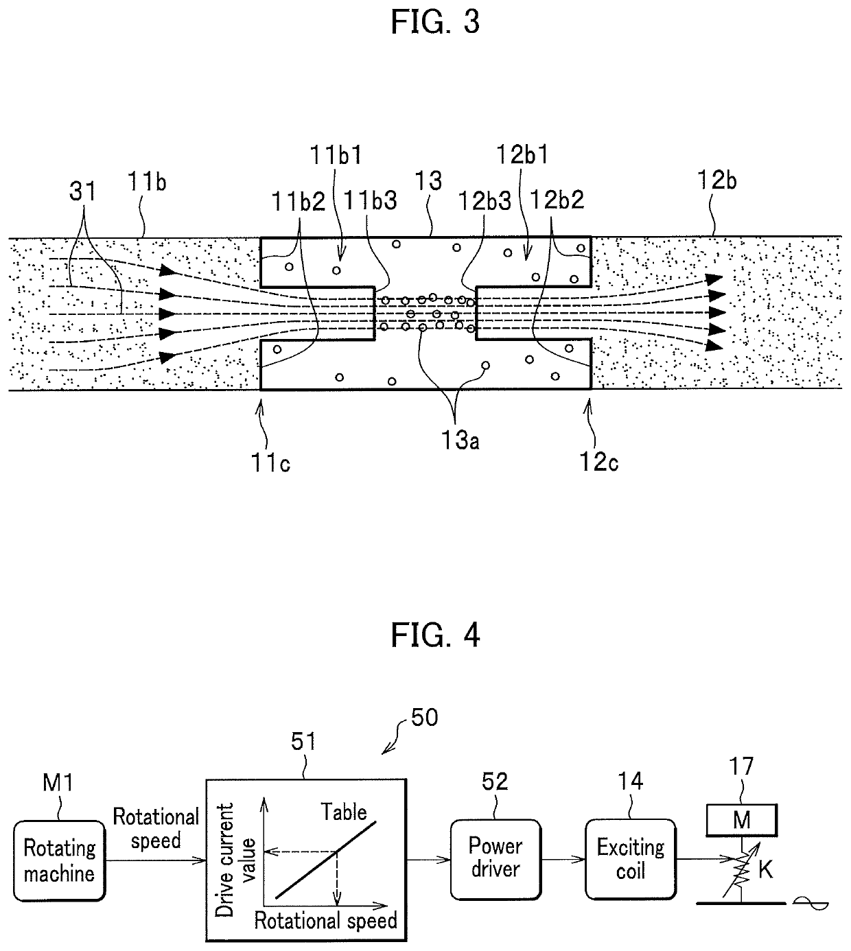
[0069]In the embodiments after the first embodiment, only shapes of the first extending part 11b, the second extending part 12b, and the magnetic viscoelastic elastomer 13 are different from those in the first embodiment, and other elements are the same as those in the first embodiment described referring FIGS. 1, 2, and 4. Accordingly, in the embodiments after the first embodiment below, shapes of the first extending part 11b, the second extending part 12b, and the magnetic viscoelastic elastomer 13 are mainly described in addition to the operation and advantageous effects, and the general description is omitted.

[0070]The same elements or parts are designated with the like references, and a detailed description is omitted.

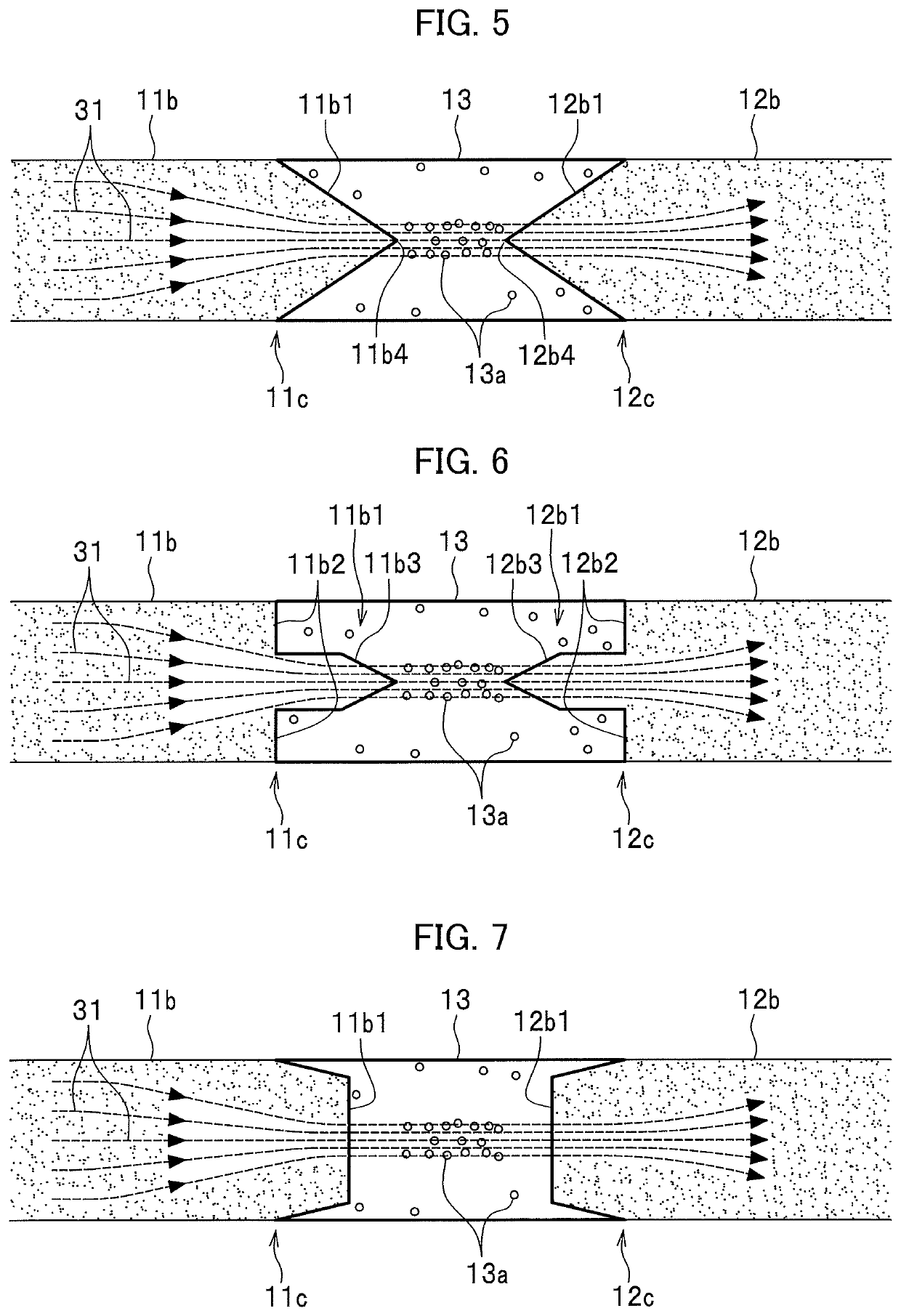
[0071]FIG. 5 is an enlarged elevational sectional view to show shapes of the first extending part 11b of the first magnetic member 11, a second extending part 12b of the second magnetic member, and a magnetic viscoelastic elastomer 13. The active vibration control...

third embodiment

[0075]FIG. 6 is an enlarged elevational sectional view to show shapes of the first extending part 11b, the second extending part 12b, and the magnetic viscoelastic elastomer 13. The active vibration controller 1 according to the third embodiment is different from the first embodiment in that the first top portion 11b3 and the second top portion 12b3 have shapes on cross section taken along the longitudinal direction of each of the top portions 11b3 and 12b3 which have sharp angles.

[0076]The magnetic flux lines 31 transmit through the extending part 11b and the second extending part 12b in the concentrated manner from the first top portion 11b3 to the second top portion 12b3, both being thin and sharp. The magnetic particles 13a are concentrated at the part of the magnetic viscoelastic elastomer 13 between the first top portion 11b3 and the second top portion 12b3. Further, this position is located between the first top portion 11b3 and the second top portion 12b3, so that it is poss...


PUM

PropertyMeasurementUnit
magnetic fieldaaaaaaaaaa
magnetic viscoelasticaaaaaaaaaa
curved shapeaaaaaaaaaa

Abstract

An active vibration controller includes: a housing; a first magnetic member on the housing, the first magnetic member including a first tip portion extending from a first base end of the first magnetic member and including a first connecting surface extending from the base end on the first tip portion; a movable member including a second magnetic member including a second tip portion extending from a second base end of the second magnetic member and a second connecting surface extending from the second base end on the second tip portion; an exciting coil; a magnetic viscoelastic elastomer having a magnetic viscoelastic property varying according to a magnetic field magnitude between the first and second tip portions, and connects the first connecting surface to the second connecting surface. The first and second tip portions are thinner than the first and second base ends, respectively.

Description

CROSS REFERENCE TO RELATED APPLICATION[0001]This application claims the foreign priority benefit under Title 35, United States Code, § 119(a)-(d) of Japanese Patent Application No. 2016-095318, filed on May 11, 2016 in the Japan Patent Office, the disclosure of which is herein incorporated by reference in its entirety.BACKGROUND OF THE INVENTION1. Field of the Invention[0002]The present invention relates to an active vibration controller.2. Description of the Related Art[0003]In the conventional passive-type absorbers, an eigenvalue of the vibration absorber is uniquely determined because a physical property of the configuration elements is fixed. Accordingly, when a frequency of the disturbance vibration agrees with the eigenfrequency of the absorber, a high damper effect is given. However, when the frequency of the disturbance vibration is different from the eigenfrequency even slightly or when the frequency of the disturbance vibration varies as time passes, i.e., in an unstable ...

Claims


Application Information

Patent Timeline
Patent Type & Authority Patents(United States)
IPC IPC(8): H02K33/02F16F1/36F16F15/03
CPCF16F1/3615F16F1/361H02K33/02F16F15/03G05D19/02
Inventor TERASHIMA, OSAMUINOUE, TOSHIO
Owner HONDA MOTOR CO LTD
Why Eureka
Try Eureka