Power converter

a power converter and converter technology, applied in the direction of electric variable regulation, process and machine control, instruments, etc., can solve the problems of increasing component cost, difficulty in producing a design that accurately and stably controls the on/off switching of the switch, etc., to reduce the derating factor of the voltage of the switch, reduce the conduction loss (or “on loss”), and increase the conversion efficiency

Active Publication Date: 2019-06-27
TDK CORPARATION
View PDF5 Cites 8 Cited by
  • Summary
  • Abstract
  • Description
  • Claims
  • Application Information

AI Technical Summary

Benefits of technology

[0018]With the power converter according to the present invention, since it is possible to use a simple configuration where an LC resonance circuit is connected in parallel to the primary winding of an isolation transformer that has a leakage inductance or a simple configuration where an LC resonance circuit is connected in parallel to an auxiliary winding of an isolation transformer, it is possible to suppress (limit) the peak voltage of a resonant voltage generated across both ends of the switch when the switch is off to around double the amplitude of the DC input voltage. Accordingly, it becomes possible to use a switch with a low withstand voltage as the switch, and since many switches with a low withstand voltage are switches with a low on-resistance, it is possible to use a switch with a low on-resistance as the switch. As a result, it is possible to reduce the conduction loss (or “On loss”) for the switch and increase the conversion efficiency. Since it is also possible to lower the derating factor of the voltage of the switch, it is possible to achieve high reliability for the switch. Also, since the power converter according to the present invention is configured so that a load network whose impedance has frequency characteristics that are set in advance, more specifically a load network with frequency characteristics with the five resonant frequencies described above or a load network with frequency characteristics with the seven resonant frequencies described above, is used as the load of the switch, the switch performs a Class E switching operation, which means that it is possible to convert a DC input voltage to a DC output voltage with higher power conversion efficiency under high frequency operation. In particular, with the configuration that has a load network with frequency characteristics including seven resonant frequencies as the load, compared to the operation waveform across both ends of the switch for the configuration that has a load network with frequency characteristics including five resonant frequencies as the load, it is possible to make the operation waveform across both ends of the switch a waveform that has a more sudden rise and fall and where the amplitude of fluctuations in a central part are suppressed, or in other words, a waveform that is closer to a rectangular waveform. This means that it is possible to further suppress the peak voltage compared to the operation waveform described above for the configuration that has a load network with frequency characteristics including five resonant frequencies as the load (that is, a waveform where the peak voltage is suppressed to around double the DC input voltage).
[0019]Also, since the power converter according to the present invention is configured so that the isolation transformer has a secondary winding with a center tap terminal, by having the rectifying and smoothing circuit rectify and smooth the voltage generated across both ends of the third and fourth resonant capacitances with the center tap terminal as a reference, it is possible to double the frequency of the current flowing to the output capacitance that constructs the rectifying and smoothing circuit. This means that if the capacitance value of the output capacitance is set equal to the output capacitance in a configuration where there is no center tap terminal on the secondary winding, it is possible to halve the output ripple voltage of the DC output voltage, and if the output ripple voltage is set equal to a configuration where there is no center tap terminal on the secondary winding, it is possible to halve the capacitance value of the output capacitance (which results in miniaturization).
[0020]Also, with the power converter according to the present invention, by constructing the isolation transformer with an auxiliary winding and connecting an LC resonance circuit in parallel to the auxiliary winding, it is possible, by appropriately setting the turn ratio between the primary winding and the auxiliary winding, to lower the voltage applied to the inductance and the capacitance that construct the LC resonance circuit compared to a configuration where an LC resonance circuit is connected in parallel to the primary winding. This means that it is possible to use low-cost components with lower withstand voltages as the inductance and the capacitance.

Problems solved by technology

That is, although the isolated resonant converter 100 is configured so that the peak voltage value of the resonant voltage that occurs when the switch 103 has been switched off is limited by the active clamp circuit 105, since the active clamp circuit 105 includes the switch 105a, there are the problems of difficulty in producing a design that accurately and stably controls on / off switching of the switch 105a and of a rise in component cost.

Method used


Image

  • Power converter
  • Power converter
  • Power converter

Examples


Embodiment Construction

[0032]Several preferred embodiments of the present invention will now be described. Note that the present invention is not limited to the embodiments given below. The component elements described below include equivalent component elements and component elements that should be apparent to those skilled in the art, and such component elements may be combined as appropriate.

[0033]Preferred embodiments of the present invention will now be described in detail with reference to the drawings. Note that in the description of the drawings, elements that are the same have been assigned the same reference numerals and duplicated description thereof is omitted.

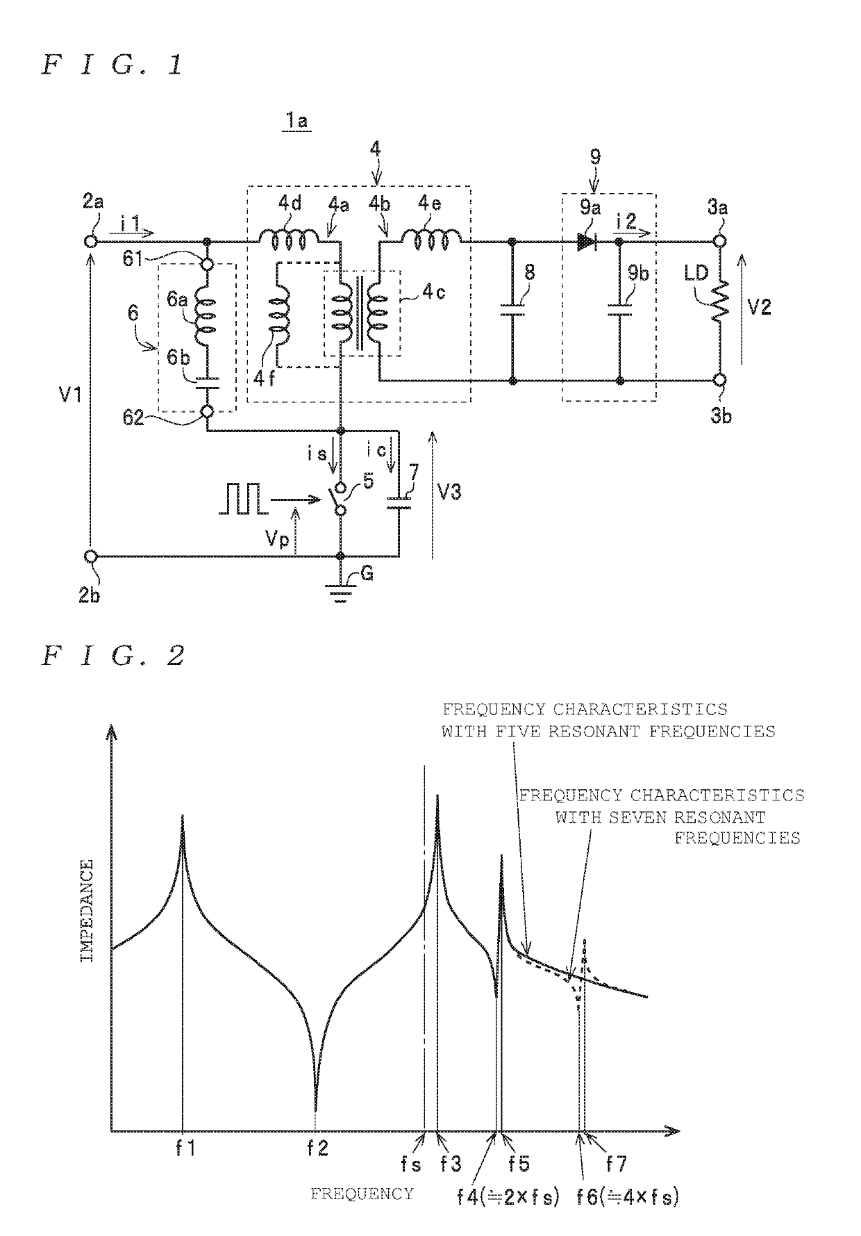
[0034]First, the overall configuration of a power converter according to a first preferred embodiment of the present invention will be described with reference to FIG. 1, with a converter 1a as one example of a power converter. The converter 1a includes a pair of DC input terminals 2a and 2b (hereinafter collectively referred to as the “...


PUM


Abstract

A power converter includes: two DC input terminals that input a DC input voltage; two DC output terminals that output a DC output voltage; an isolation transformer with a primary winding and a secondary winding; a switch that is connected across the two DC input terminals in a state where the switch is connected in series to the primary winding and that switches the DC input voltage; an LC resonance circuit that includes an inductance and a capacitance and is connected in parallel to the primary winding; a first resonant capacitance that is connected in parallel to the switch; a second resonant capacitance that is connected in parallel to the secondary winding; and a rectifying and smoothing circuit that rectifies and smoothes a voltage generated across both ends of the second resonant capacitance and outputs as the DC output voltage across the two DC output terminals.

Description

FIELD OF THE INVENTION[0001]The present invention relates to a power converter.DESCRIPTION OF THE RELATED ART[0002]An isolated resonant converter with high conversion efficiency is known as a power converter circuit that operates in a high frequency band (see Patent Literature 1 (Japanese Laid-open Patent Publication No. 2017-508437)).[0003]As depicted in FIG. 9, the isolated resonant converter 100 disclosed in Patent Literature 1 includes a transformer 101 (or “isolation transformer”) with a primary winding 101a, a secondary winding 101b, and an auxiliary winding 101c, a switch 103, which is disposed so as to be connected in series with the primary winding 101a between direct current (DC) input terminals 102a and 102b and switches a DC input voltage V1 inputted across the DC input terminals 102a and 102b, a resonant capacitor 104 connected in parallel to the switch 103, an active clamp circuit 105, an LC resonance circuit 106 (a series circuit composed of an inductance 106a and a c...

Claims


Application Information

Patent Timeline
Patent Type & Authority Applications(United States)
IPC IPC(8): H02M3/335H02M1/08
CPCH02M3/33523H02M2001/0058H02M1/083H02M3/28H02M3/335H02M1/32H02M1/0038H02M1/0048H02M3/33507Y02B70/10H02M1/0058
Inventor LIN, MINMATSUURA, KEN
Owner TDK CORPARATION
Why Eureka
Try Eureka