
Machining system

Active Publication Date: 2019-07-04
MAKINO J
View PDF0 Cites 0 Cited by
  • Summary
  • Abstract
  • Description
  • Claims
  • Application Information

AI Technical Summary

Benefits of technology

The present invention provides a machining system with a setup station that has a maximized opening width with a simple structure. The system has a setup operation mode and a workpiece transfer operation mode, and the interlock mechanism ensures that the operator-side and the pallet transfer device-side are isolated from each other during the entire operation process. The system improves safety for the operator by allowing movement operations of the pallet transfer device regardless of the opening or closing of the operator door. The interlocking mechanism consists of two pulleys and two wire ropes, and the operator performs the rotation operation of the outer door using both hands to prevent finger injury.

Problems solved by technology

In the setup station described in Patent Literature 1, since the operation angle of the outer door is less than 180°, there is a problem in that even when the operator door is fully opened, the opening width when the operator accesses a pallet on the setup table and a workpiece fixed to the pallet is small.
In the setup station described in Patent Literature 2, there is a problem in that it is necessary to provide ring gears at the lower ends of each of the door elements, whereby the manufacturing cost of the setup station increases dramatically.

Method used


Image

  • Machining system
  • Machining system
  • Machining system

Examples


Embodiment Construction

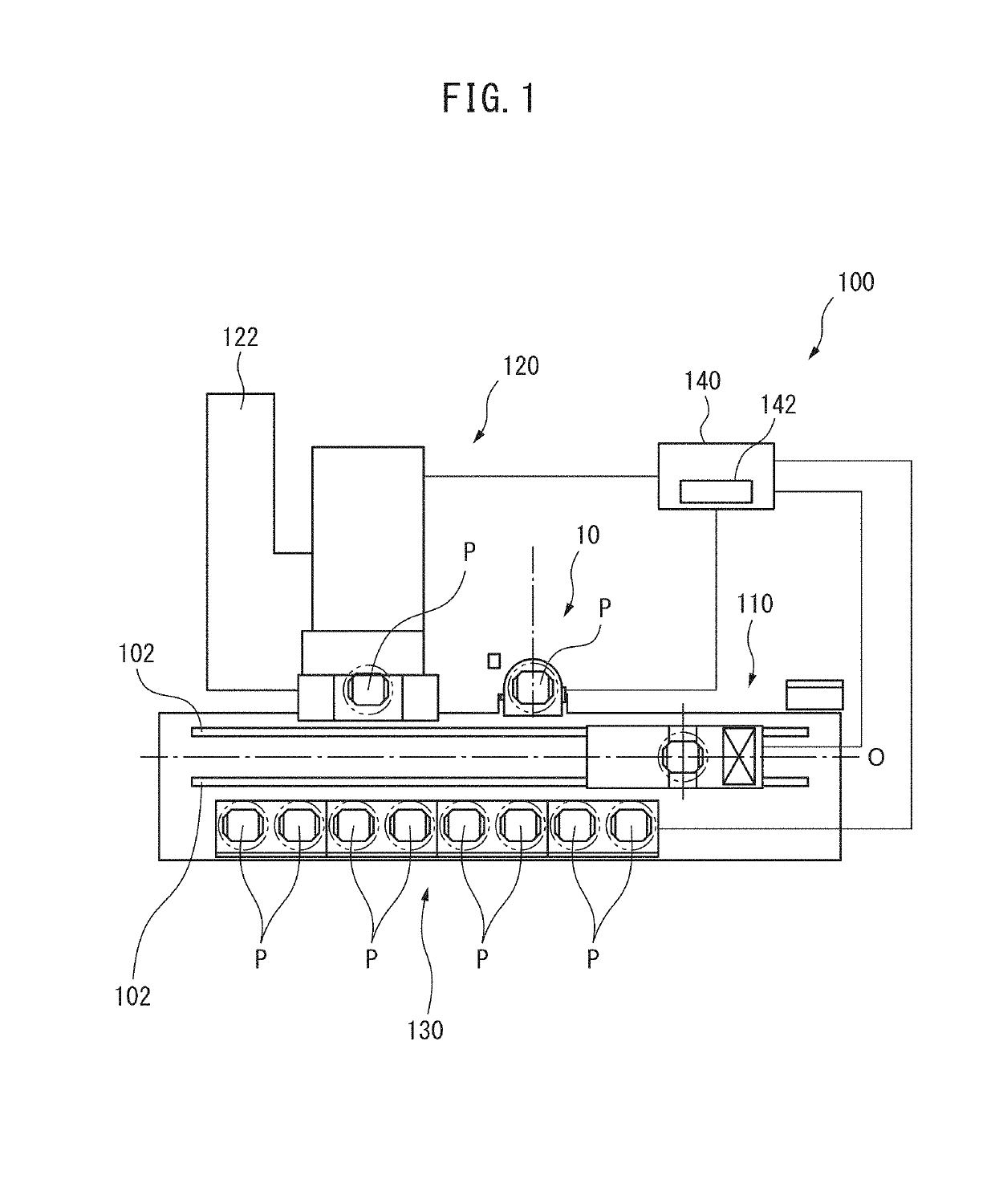
[0030]With reference to FIG. 1, which is a schematic view of a machining system according to a preferred embodiment of the present invention, the machining system 100 comprises a pair of rails 102 which extend along a central axis line O and which form tracks for a pallet transfer device 110, a setup station 10 arranged on one side of the rails 102, a processing machine 120, and a pallet stacker 130 arranged on the side opposite the setup station 10 and the processing machine 120. The pallet transfer device 110 moves between the setup station 10, the processing machine 120, and the pallet stacker 130 along the rails 102 to convey and transfer pallets P on which workpieces W are attached.

[0031]The processing machine 120 can be a machining center comprising a spindle having a tool mounted on a tip thereof, a table, arranged so as to face the spindle, for attaching a pallet to which a workpiece is attached, and at least X, Y, Z orthogonal three-axis feed shafts for moving the spindle a...


PUM


Abstract

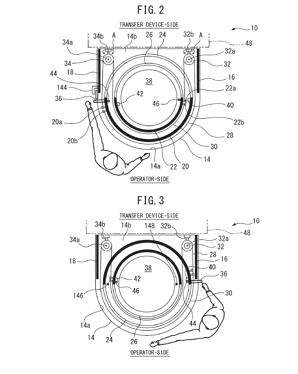
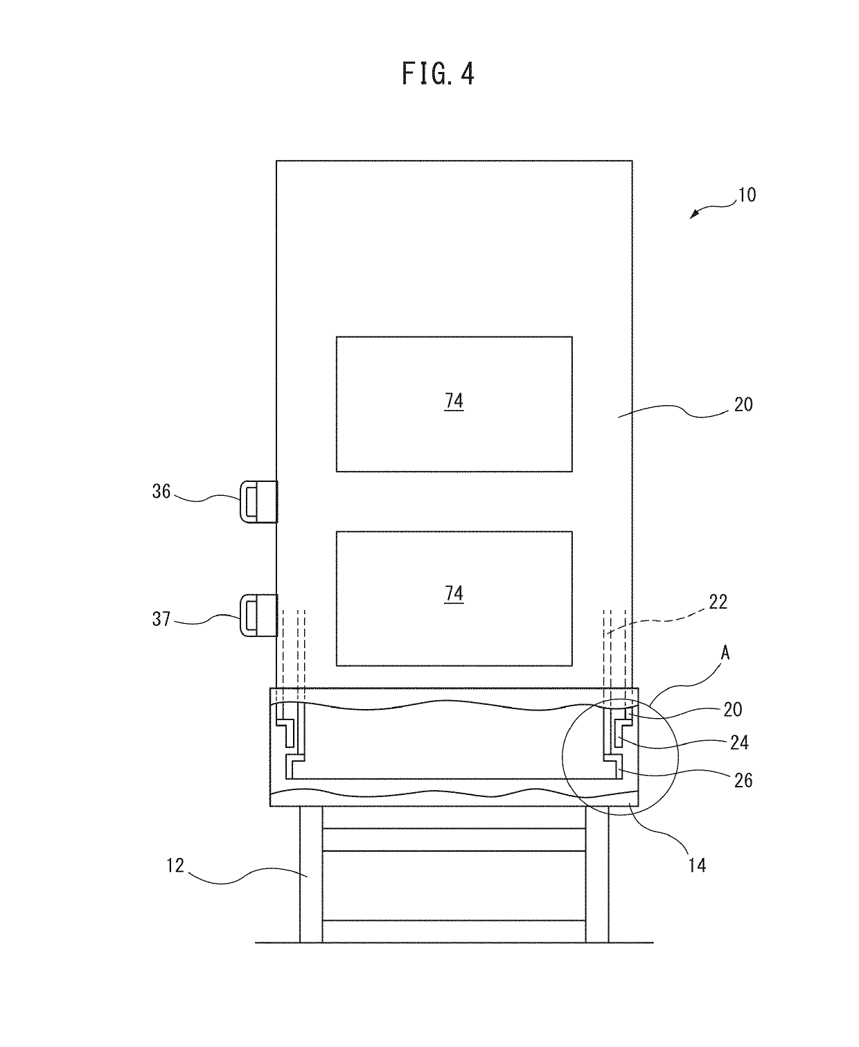
A machining system comprises: a machining device that machines a workpiece; a set-up station with which pallet workpiece attachment / detachment is carried out; and a pallet conveyance device that conveys the pallet between the machining device and the set-up station. A partially cylindrical operator door, which can rotate around a set-up table on which the pallet is mounted, includes a partially cylindrical outer door and a partially cylindrical inner door which rotate following coaxial circular trajectories of different radii. The set-up station is provided with an interlocking mechanism that causes the outer door and the inner door to rotate in an interlocked manner so that a shielded state is constantly maintained between the operator side and the pallet conveyance device side.

Description

CROSS-REFERENCE TO RELATED APPLICATIONS[0001]This application is a U.S. national phase patent application of International Patent Application No. PCT / JP2016 / 076682, filed Sep. 9, 2016, which is hereby incorporated by reference in the present disclosure in its entirety.FIELD OF THE INVENTION[0002]The present invention relates to a machining system comprising one or a plurality of processing machines for machining a workpiece, a setup station for performing attachment and detachment of the workpiece to and from a pallet, and a pallet transfer device for conveying and transferring a pallet on which the workpiece is fixed between the processing machine and the setup station.BACKGROUND OF THE INVENTION[0003]Conventionally, in machining systems comprising one or a plurality of processing machine for machining a workpiece, a setup station for performing attachment and detachment of a workpiece of a pallet, and a pallet transfer device for conveying and transferring a pallet on which the wo...

Claims


Application Information

Patent Timeline
IPC IPC(8): B23Q7/04B23Q11/08B23Q7/05
CPCB23Q7/047B23Q11/08B23Q7/05B23Q11/0891B23Q11/0825B23Q7/1426B23Q11/0092B23Q2210/006B23Q7/00B23Q11/00
Inventor MAENOSONO, TAKUDAIYOSHIDA, TAKAHIROUCHIDA, NOBUHIROAOYAMA, YUICHI
Owner MAKINO J
Learn More