Supercharge Your Innovation With Domain-Expert AI Agents!

Method and system for controlling powered anode drive level

a technology of anode drive and power supply, applied in the field of cathode protection system, can solve the problems of not being able to adjust for varying tank and water conditions, corroding other components, and producing inacceptable amounts of hydrogen gas

Active Publication Date: 2019-07-04
COPELAND COMFORT CONTROL LP
View PDF0 Cites 0 Cited by
  • Summary
  • Abstract
  • Description
  • Claims
  • Application Information

AI Technical Summary

Benefits of technology

The patent describes a method and system for controlling a powered anode in a vessel. The system uses an anode drive power supply and an anode drive controller to vary the electrical power input and measure different electrical parameters, such as current and voltage, during operation. The controller analyzes the measured data and determines the slope of the current value with respect to previous values. When a discontinuity is detected, the controller applies the current value of a different electrical parameter to the power input. This approach allows for smoother operation of the powered anode and improves its overall performance.

Problems solved by technology

Insufficient current provides insufficient protection, excessive current may result in corrosion of other components.
Greatly excessive current may result in the production of unacceptable amounts of hydrogen gas.
Simple powered anode systems often used a fixed current based on a vessel's size which provided some general level of protection, but could not adjust for varying tank and water conditions.
Fixed current systems cannot adjust for tank lining deterioration, various water conditions and other changes over time and installation location.

Method used


Image

  • Method and system for controlling powered anode drive level
  • Method and system for controlling powered anode drive level
  • Method and system for controlling powered anode drive level

Examples


Embodiment Construction

[0020]The following detailed description illustrates embodiments of the disclosure by way of example and not by way of limitation. It is contemplated that the disclosure has general application to corrosion protection in industrial, commercial, and residential applications.

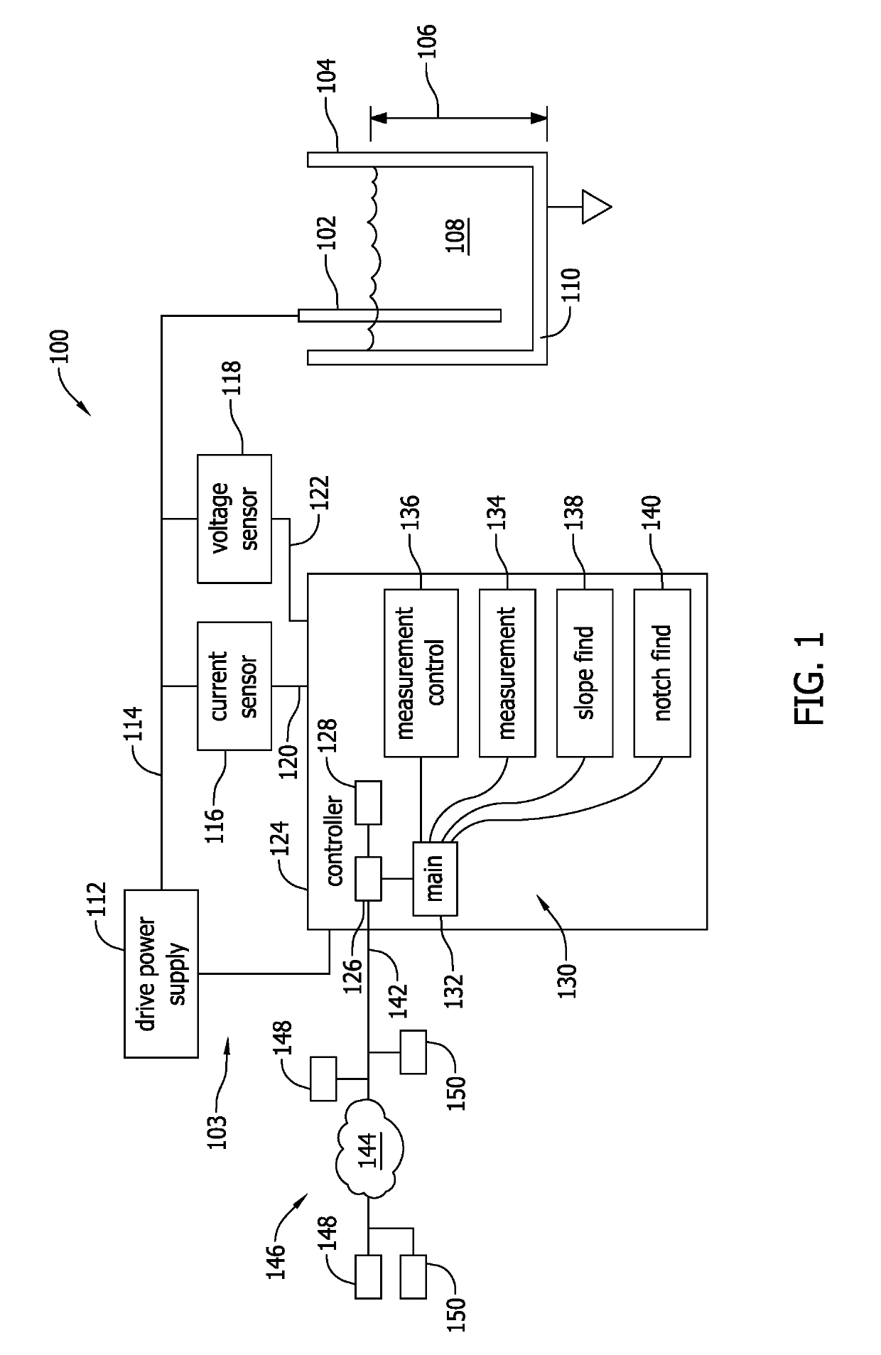
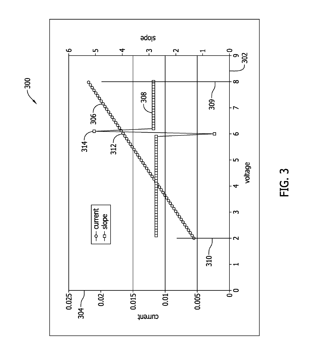
[0021]Embodiments of a cathodic protection anode drive system are described herein. For example, a non-sacrificial anode is positioned within a vessel, such as, but not limited to a water heater and the anode is electrically coupled to a drive circuit, which, as closely as possible, counter-balances the drive voltage of the anode to the cathodic demands of the vessel. To be effective the drive voltage is varied over time to match changing conditions within the vessel. Such conditions include, but are not limited to, changes in fluid chemistry, changes in fluid temperature, changes in fluid level in the vessel, and combinations of the above. The method of operation of the system is based on an observable notch in a...


PUM

PropertyMeasurementUnit
electrical parameteraaaaaaaaaa
currentaaaaaaaaaa
electrical parametersaaaaaaaaaa

Abstract

A system and methods of controlling a powered anode are disclosed. The method includes varying an electrical power input driving the powered anode through a range of values of a first electrical parameter, the range defined by an upper range limit and a lower range limit and measuring a current value of a second electrical parameter of the electrical power input during the varying. The method also includes determining a slope between the measured current values of the first and corresponding second electrical parameters and measured previous values of the first and second electrical parameters and comparing the determined slope to a predetermined slope threshold range and applying the current value of a first electrical parameter to the electrical power input when a discontinuity in the slope is determined.

Description

FIELD[0001]This disclosure relates generally to cathodic protection systems, and, more particularly, to an anode drive system for a fluid vessel.BACKGROUND[0002]Anodes, either active or powered, or passive (sacrificial) are used to limit, control, and / or prevent galvanic corrosion damage to the tank of water heaters and other metal water vessels. Both passive and active systems protect the tank by being a more active anode than the tank. Passive or sacrificial systems generally use magnesium (Mg) and / or aluminum (Al) rods electrically coupled to the tank. This anode rod is consumed in the process of protecting the tank, hence the use of the term sacrificial. Active systems generally employ a permanent anode rod that typically includes, for example, a titanium alloy. The rod is connected to a power supply which applies the current necessary to null the galvanic effect. Insufficient current provides insufficient protection, excessive current may result in corrosion of other components...

Claims


Application Information

Patent Timeline
Patent Type & Authority Applications(United States)
IPC IPC(8): C23F13/04G05B19/042C23F13/22
CPCC23F13/04G05B19/042C23F13/22G05B2219/25268C23F2213/10C23F2213/30F24H9/455
Inventor ARENSMEIER, JEFFREY N.
Owner COPELAND COMFORT CONTROL LP
Features
  • R&D
  • Intellectual Property
  • Life Sciences
  • Materials
  • Tech Scout
  • Unparalleled Data Quality
  • Higher Quality Content
  • 60% Fewer Hallucinations
Learn More